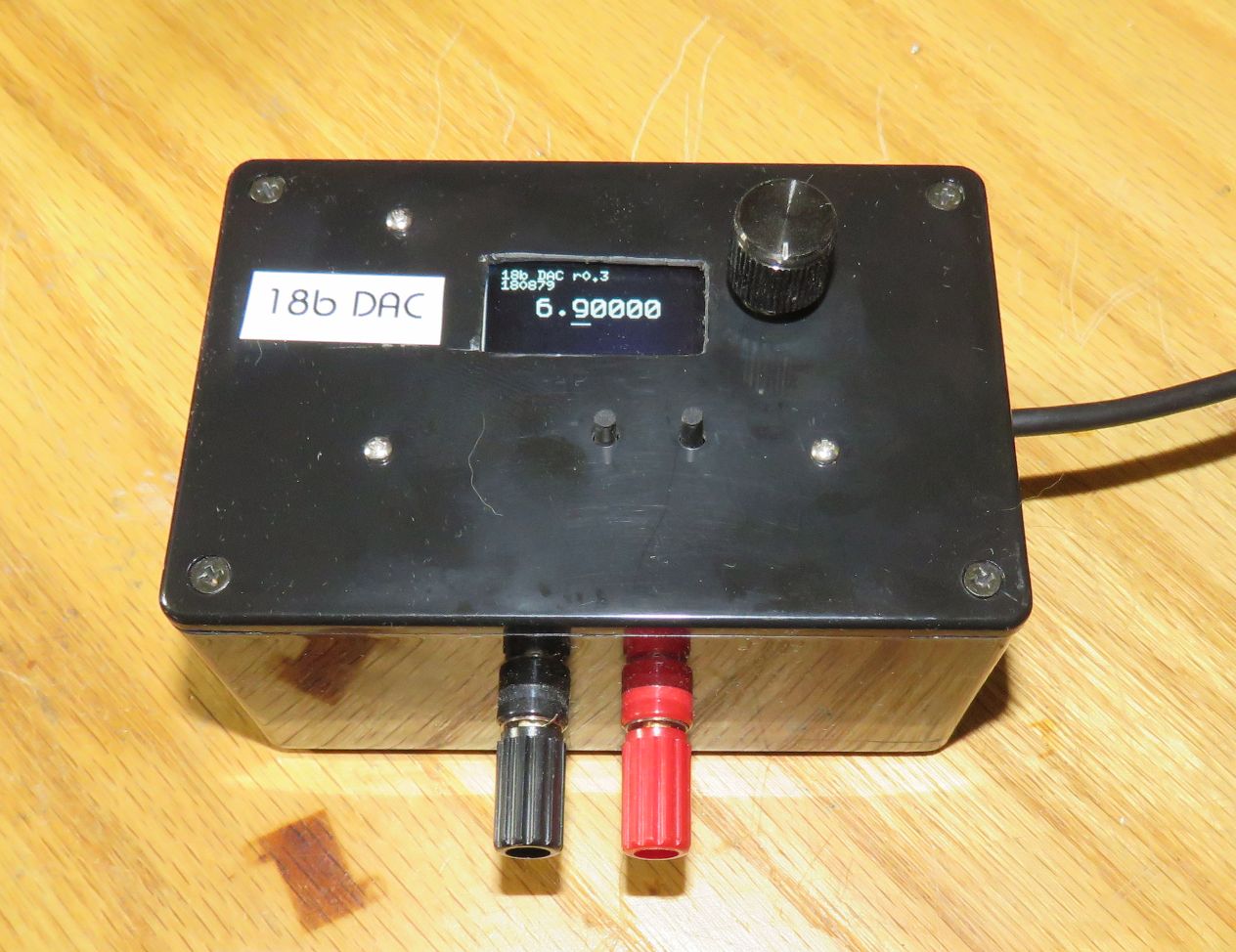
18 bit
DAC: Precision Voltage Source
The
Blog for this project
The
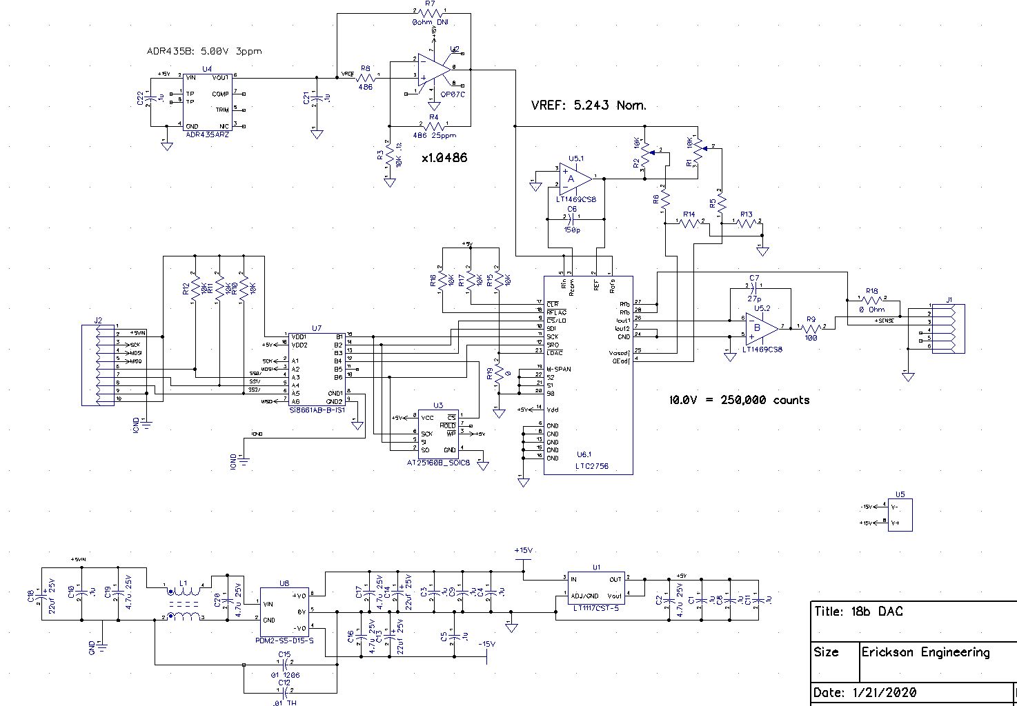
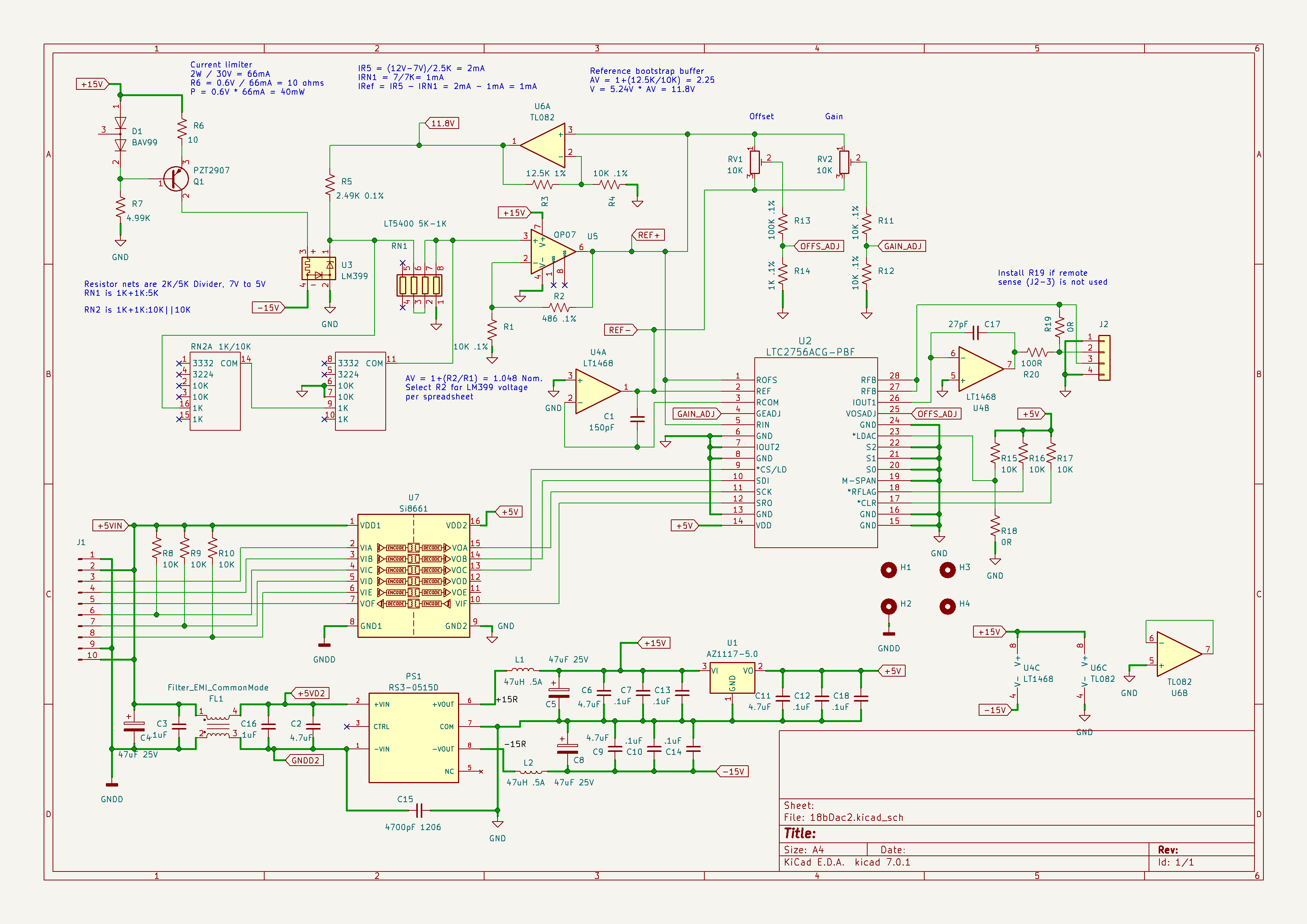
Schematics, PCB files, and Simulation
models are
here
Youtube Video on this project (Coming
soon)
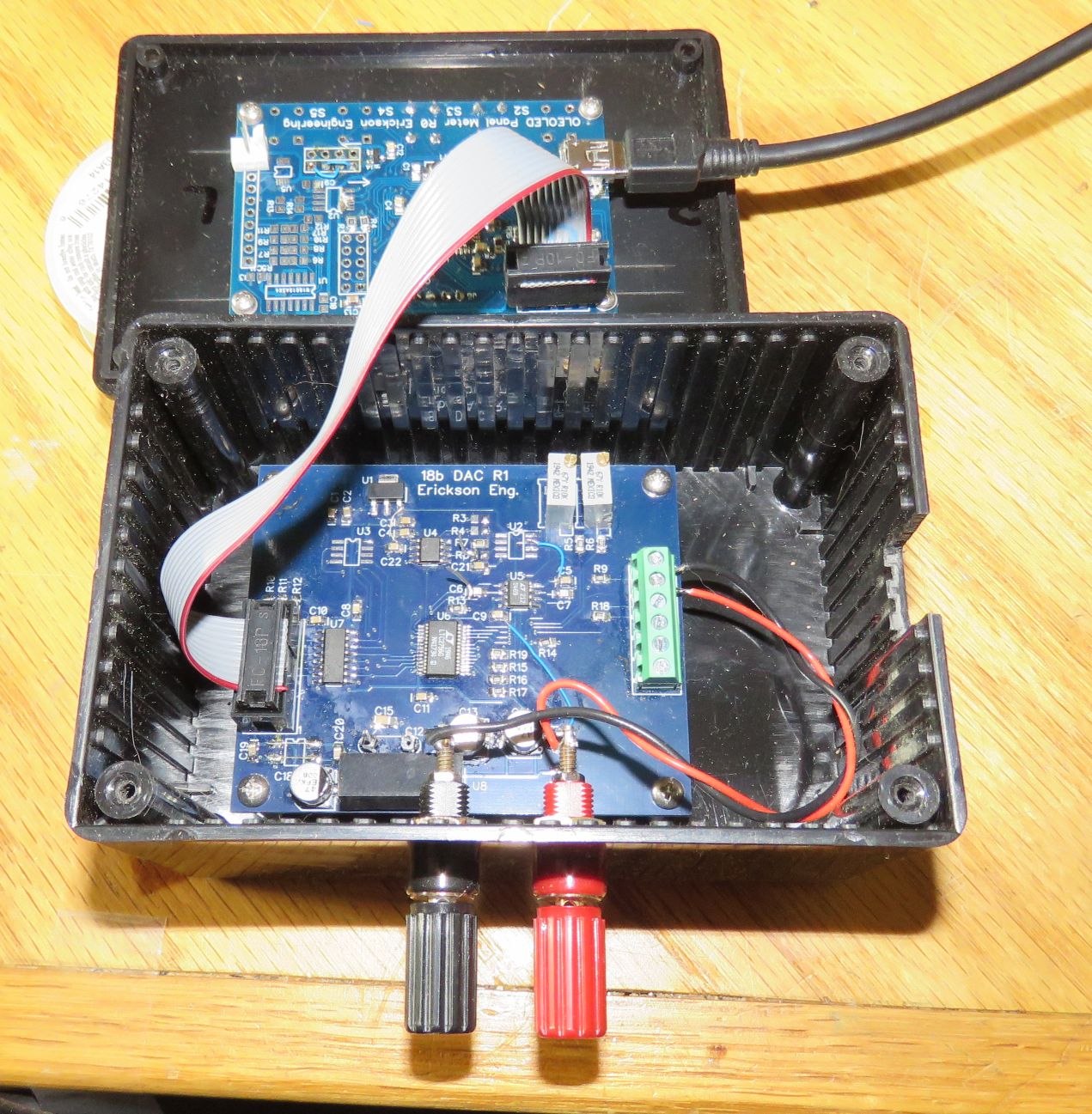
LachlanGunn/OICI began with the OIC library. I got it working on Teensy and on ATMEGA, and was happy with how quickly it came up. 18b DAC was crying for a proper way to control it via USB. And unlike DIY-SMU, the 18b DAC is a simple project: Set the DAC to a voltage, done! I moved the code to the LeoLed I use to control the 18b DAC. The code fits, but is a tight squeeze on the ATMEGA32U4 processor. Between the U8G2 library (with large fonts) and the SCPI Parser with floating point math, it's up to about 23K of the 28K available flash memory. For RAM, I use ~2K of the 2.5K available. As long as I avoid too much feature-creep, it should be OK. I'd like to implement SCPI on my E-Load project soon, as well as on the upcoming Switch (MUX) project. Both of these projects plan to use use LeoLed on a 'MEGA32U4. The Vrekrer and OIC libraries are about the same size.
This one was easy to install and to run the examples. I like that the basic example uses Arduino analog I/O. I found it to be a bit touchy: It seems to hang if you send it bad SCPI commands. Interprets floating point numbers fine. To specify commands is slightly cumbersome, requiring you to specify both the long and short forms as well as the string lengths.
source = scpi_register_command(ctx.command_tree, SCPI_CL_CHILD, "SOURCE", 6, "SOUR", 4, NULL);
scpi_register_command(source, SCPI_CL_CHILD, "VOLTAGE", 7, "VOLT", 4, set_voltage);
Vrekrer SCPI Parser
Also easy to install this library and run the basic example. The basic example is a dimmer, and controls an LED brightness. Command register format is more convenient. Just call out the name once, and no need to specify string lengths. Interprets Floating point fine. So far so good, I'll stick with this one for now. BTW F("stuff") causes the string to live in Flash memory. I did not know that.
my_instrument.SetCommandTreeBase(F("SOURce"));
my_instrument.RegisterCommand(F(":VOLTage"), &SetVoltage);
my_instrument.RegisterCommand(F(":VOLTage?"), &GetSourceVoltage);
Jaybee.cz/scpi-parser
This one is not a native Arduino library. It it quite large, about 10 .h files and another 8 .c files. I spent a day trying unsuccessfully to coax it to compile on a Teensy, and then gave up. A real programmer could probably do it.