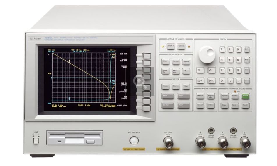
Agilent
4395A 500MHz Network/Spectrum / Impedance Analyzer
Power Supply Repair
Also should apply to 4396A 1.8GHz
YouTube Video (but not yet)
Yet another $40,000 Power Supply repair
story
Why $40,000? I am responsible for a few Agilent 4395A 500MHz
Network/spectrum/impedance analyzers. 2 of them are dead or
recently defunct. These are ~$20,000 (new) machines,
both with dead 24V power supplies. These are great instruments
used at my day job for many tasks, particularly measuring
ultrasound transducer impedance in the 10-100MHz range. One has
been hacked back into operation, the other one is dead.
These instruments are no longer built. The power supplies are
built by Artesyn, with no schematics available, of course. Agilent
(now Keysight) might be able to repair it, I didn't look into that
option. In fact, I notice that these instruments have even less
repair information in their owner and service manuals than other
HP / Agilent RF equipment. Not even a system block diagram! Come
on, Agilent!
When one unit died a few years ago, I was in a hurry to get it
back up and running. Its power supply is a fairly generic 24V
switcher, I'm guessing about 150-200 Watts. A second board in the
instrument takes the 24V and converts it to all the instrument
operating voltages. I had a few 24V switchers lying around, and
hacked in a 24V, 115W Condor supply. The instrument came right up.
I measured the 24V DC current which was close to 5A. Since the
first power supply I chose was only 115W, or 115W/24V = 4.8A max,
I didn't feel comfortable having the supply operate so close to
its maximum. I found a larger, 250W supply and mounted it in the
unit. For cabling I adapted the existing cables to the new supply.
I built a quickie, flat aluminum bracket to adapt the power supply
to the instrument. It worked swell. See the photos below. I
put the dead power supply aside and put the instrument back into
service.
Then in early 2020, a second 4395A acted up. It was intermittent
and would work for a few months and then die for a week. Finally
it died for good in early 2021. I opened it up and sure enough, no
+24V. Deja-vu all over again. Time to repair the old supply, and
if I'm real lucky, the other unit will have the same problem. You
know, kill two stones with one bird.
The AC input connector is a 5 pin 0.156" Molex / Amp connector
with only 3 pins loaded. I wired up a power cable to power it up
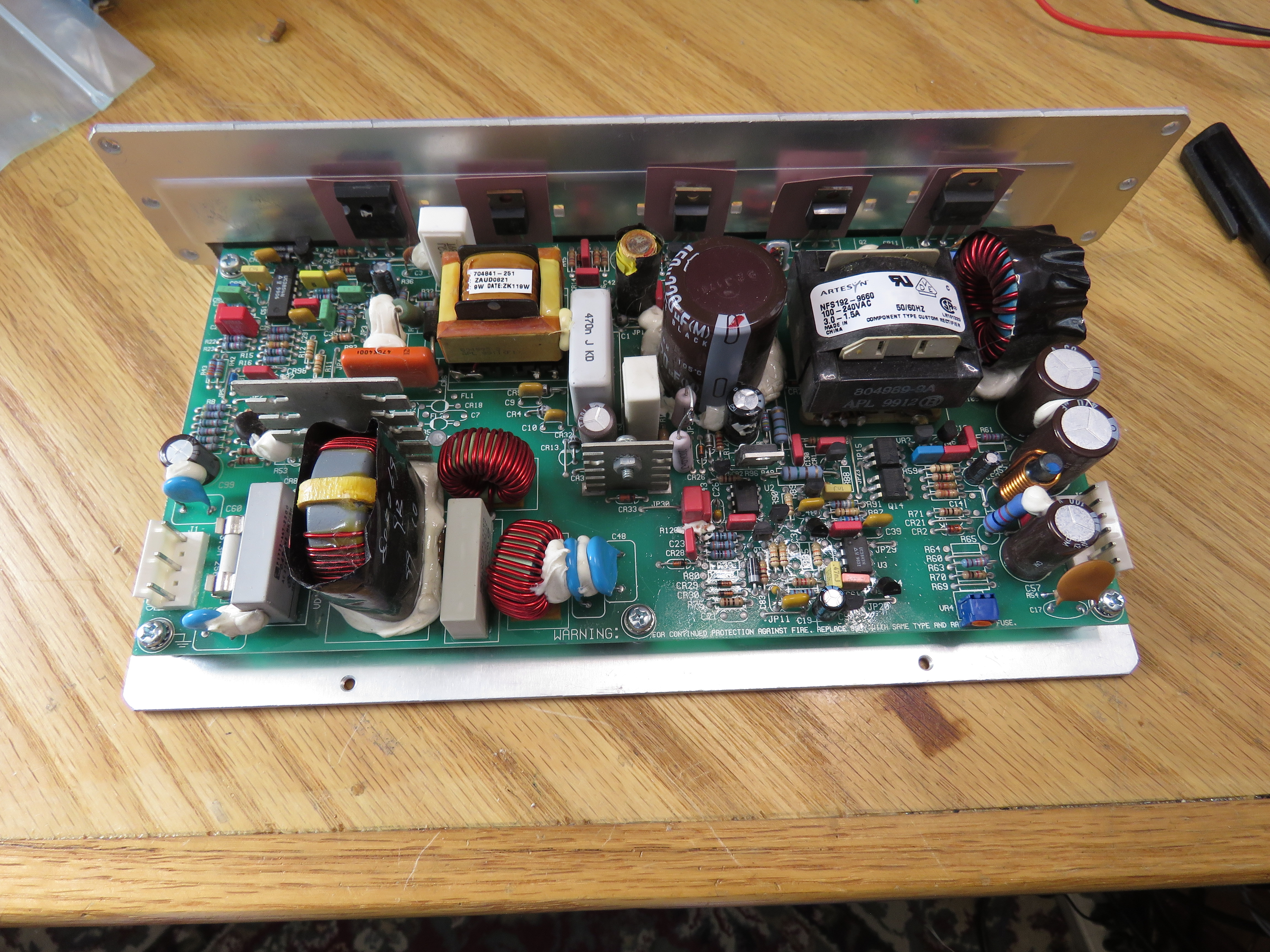
on the bench. To do proper proper measurements, and to see the
circuit traces which are all on the back of the board, I removed
the PC board. This was straightforward: remove 5 screws, one
snap-on plastic spacer, and 5 transistor heat sink mounting clips.
For safety, I should have used an isolation transformer, but did
not have one handy. So I couldn't use a scope to view signals,
just a DMM.
First, I (again) visually inspected the components and PCB traces.
No visible damage, capacitor leakage, or bulging capacitors. No
darkened components or PCB areas. No bad smell.
There are only 3 ICs on the power supply board: UC3854, and
UC3843, and an LM399 (comparator). The UC3854 is a Power Factor
controller. The UC3843 is a current-mode switching supply
controller. Both of these drive 800V power FETs. I pulled the data
sheets of the controllers to see the basic circuitry. I assumed
that the general schematic of the power supply would be close to
the block diagrams on the data sheet.
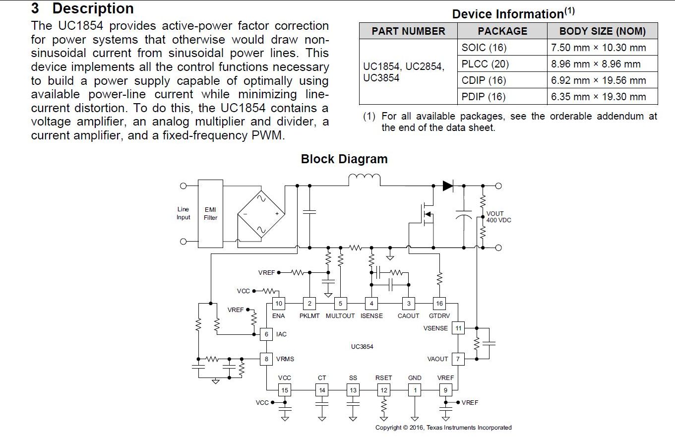
Here is the typical UCx854 Power factor controller circuit. Its
job is to charge the main filter capacitor without the high
current, fast pulses that would result from a simple
diode-capacitor circuit. It cleverly controls the PWM of a flyback
circuit to make the input current approximate a sine wave.
European regulatory standard IEC 61000-3-2 limits line current
harmonics, in order to prevent distorting the overall power grid.
To meet the standard, line voltage current harmonics must be
limited, particularly on power supplies > 80Watts. See https://en.wikipedia.org/wiki/IEC_61000-3-2
These two "typical application" schematics from the IC data sheets
are great. Combined, they pretty much show the major components of
this power supply.
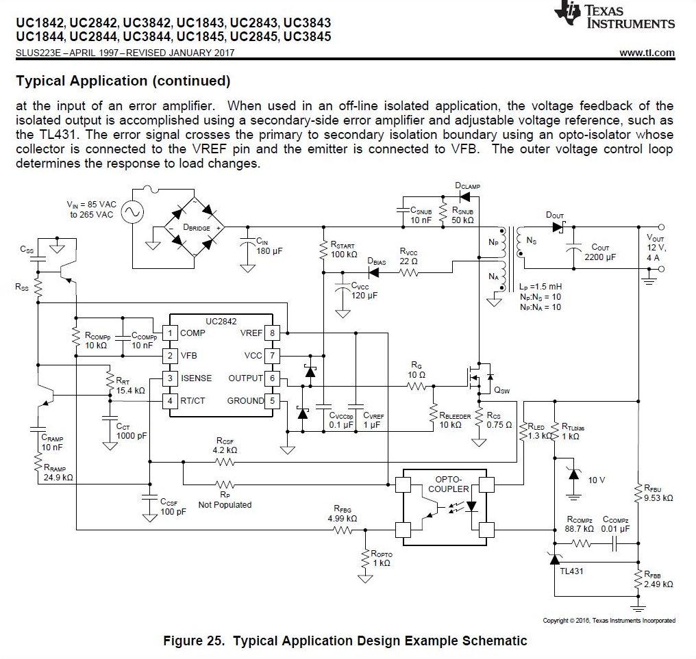
Below is a 'typical' UC3843 Current mode controller circuit for a
+12V 50W power supply. It controls the DC-DC converter which
converts line-connected +400VDC on the main filter cap to an
isolated (grounded) +24VDC. It does so by controlling the
pulse-width of the PowerFET that switches the +400V to the main
transformer.
In the 4395A supply, there are 2 power-FETS. The circuit looks
like a conventional half-bridge; there is a large film capacitor.
But I don't see a high-side gate-drive transformer. So the precise
circuit is a mystery to me. But hey, my job here is to fix
this thing, not to over-analyze it. Some level of understanding is
necessary to get the job done.
A few measurements: Fault Found!
I measured the voltage on the main filter
capacitor, and it was about +160V This means the AC input fuse,
line filter, rectifier and main 450V filter capacitor are
basically working. It did not occur to me that the low voltage
meant that the UC1854 and its FET were not working. If they were,
the voltage on the main filter cap would be +400V, not +156V. But
I moved on to the current mode controller anyway. Ignorance is
bliss.
I next measured UC3843 VCC (VCC pin 7 to GND pin 5) and it was
about +0.6V. It should be about 15V. This meant the controller IC
was not getting either the startup voltage via Rstart or the
running voltage via Rvcc and Dbias. So either Rstart was open or
Cvcc (120uF) or the UC3843 was shorted. I found two 220K ohm 1/2W
resistors on the board, figuring one of them was Rstart. One
measured 220K ohms in circuit and the other measured > 5Meg. I
un-soldered the open 220K from the board and it measured open. I
checked the circuit and these two 220K resistors are in series
between the +400V and the UC3843, so Rstart is 2 x 220K or 440K
ohms. Each resistor burns P = V^2 / R = 200V * 200V / 220K =
0.18W. I replaced the dead resistor with two 100K power resistors
in series (200K) and the power supply powered up, providing +24V.
Hooray!
At this point the main capacitor measured 400V, meaning that the
two controller ICs are somehow connected: without the Current
controller working the Power factor controller also doesn't work.
I don't understand it, but I don't care. Problem solved! I also
don't understand why the 0.5W resistor burning 0.18W failed. Bad
resistor I assume. I ordered a handful of 220K 2Watt resistors so
I can replace both of them in both power supplies. Now on to
troubleshoot Supply #2
Supply 2: Deja-vu all over again
The repaired supply was installed in the unit,
and it powered up and operates fine. I removed the power supply
from the 2nd unit, immediately went to the 220K resistors, and as
I surmised, one was open. I replaced both resistors and the 24V
supply came up. Happy day! I removed the hacked power supply and
wiring adapters, installed the original supply, and all is
well. These 220K resistors appear to be 'normal' low-cost carbon film 1/2 watt
resistors. Body size is 9mm x 3mm. They don't appear to be power
rated, not flame retardant, not surge rated. I suspect that the
problem with them is that they did not like having 200V applied,
and ultimately failed. I checked several resistor data sheets and
all 1/2 watt resistors are rated 300V or more. Moral of the story?
Don't apply 200V to a cheap resistor.
While I had the supply on the bench, I tested it
at full load. It puts out 10A and goes into current limit at
10.3A. I suspect the power supply is designed for 7-8 amps
continuously. As I stated above, the instrument draws about 5A.
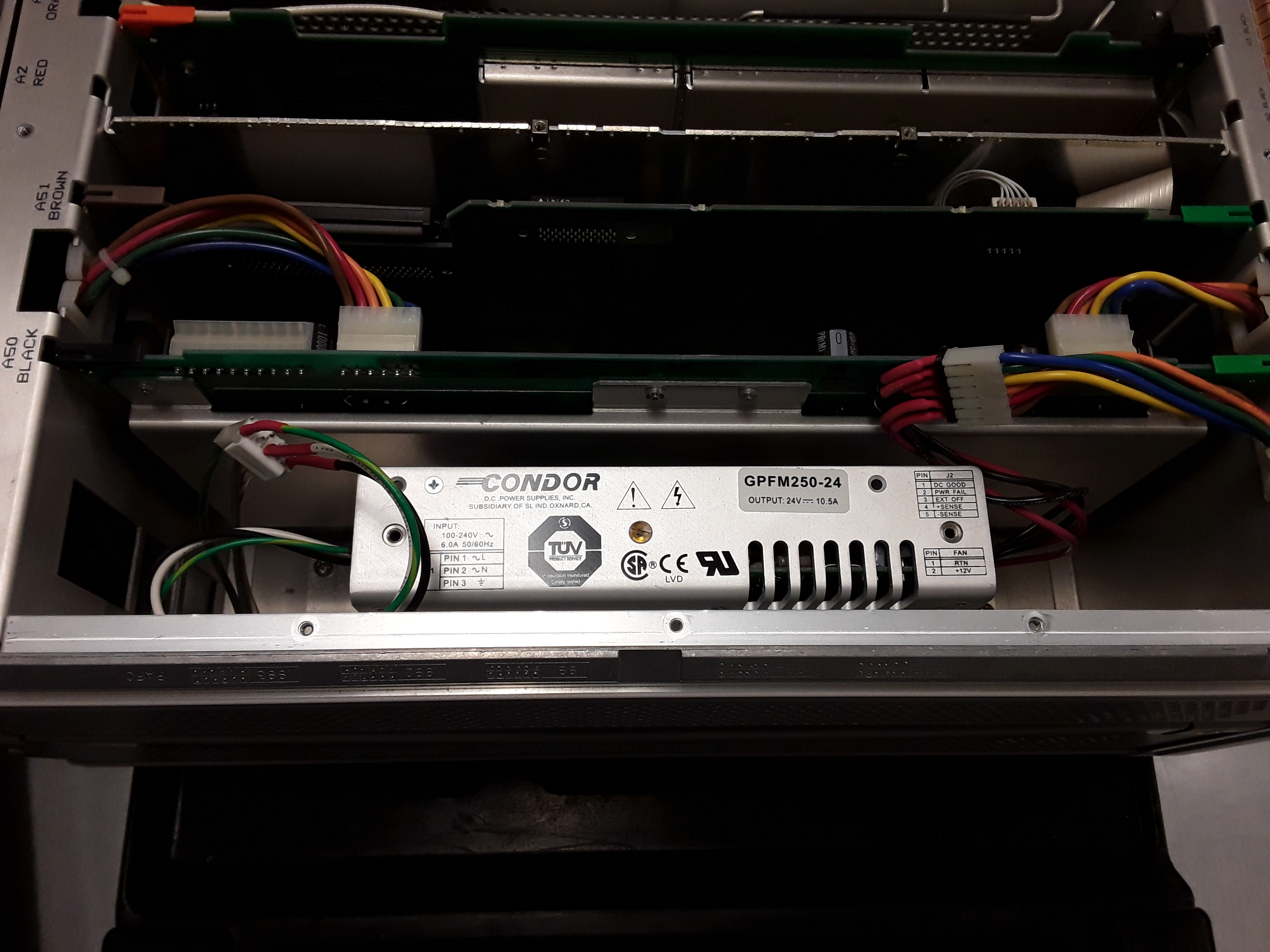
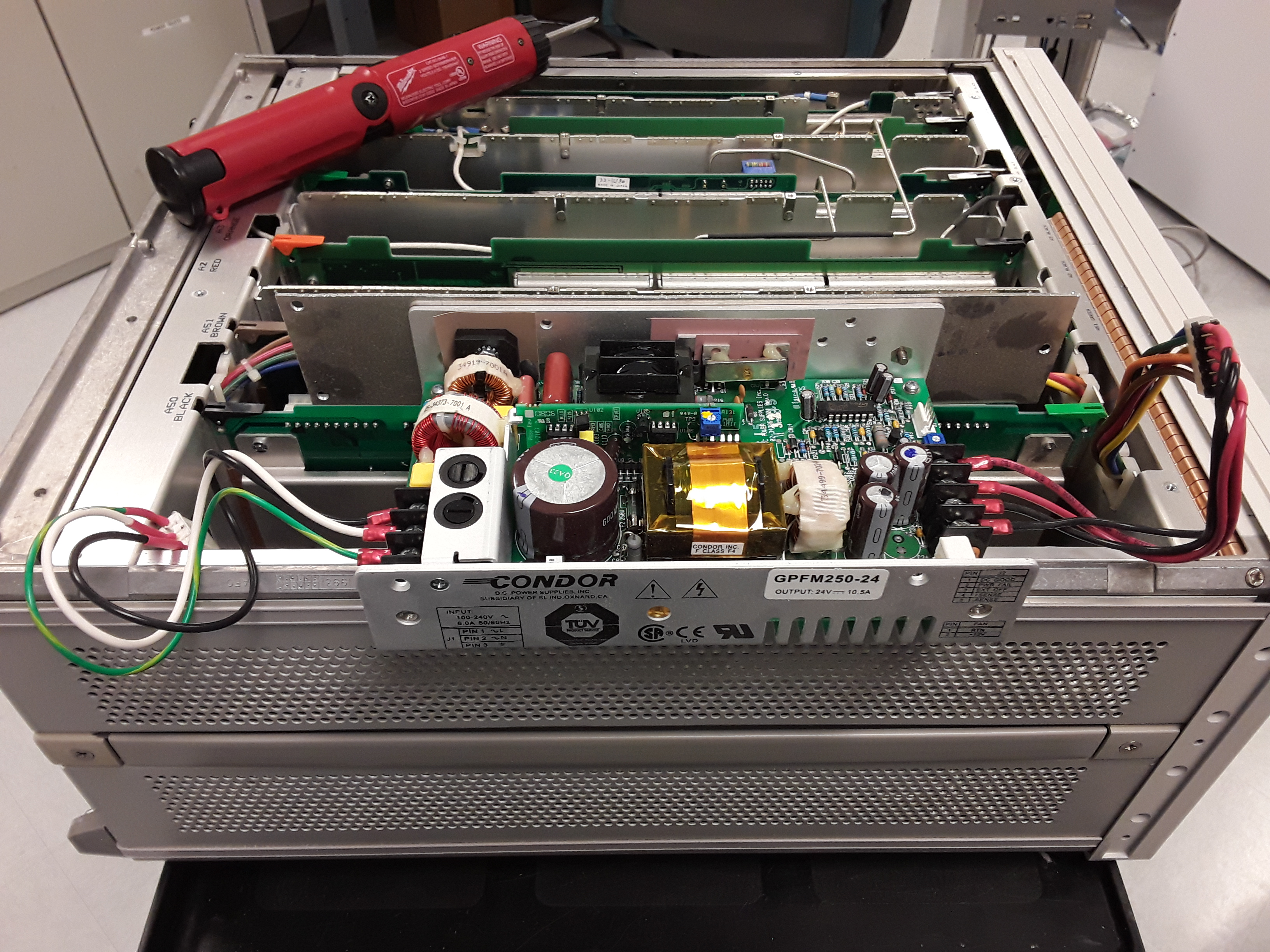
Hacked 24V power supply.
Here is the power supply that I hacked into the
first broken unit. It is a Condor GPMF250-24, a 24V, 10A, 250W
power supply. It worked very well. Of course, you don't have to do
this hack if you can repair the original supply.
Note the flat sheet metal bracket that adapts the Condor supply
mounting holes to the 4395A mounting holes. Also note the 2
adapter cables, custom made to adapt the Molex 0.156" pin
connections of the original supply to the Condor screw terminals.
I didn't want to modify the instrument so that the original supply
could be easily reinstalled. Glad I didn't.