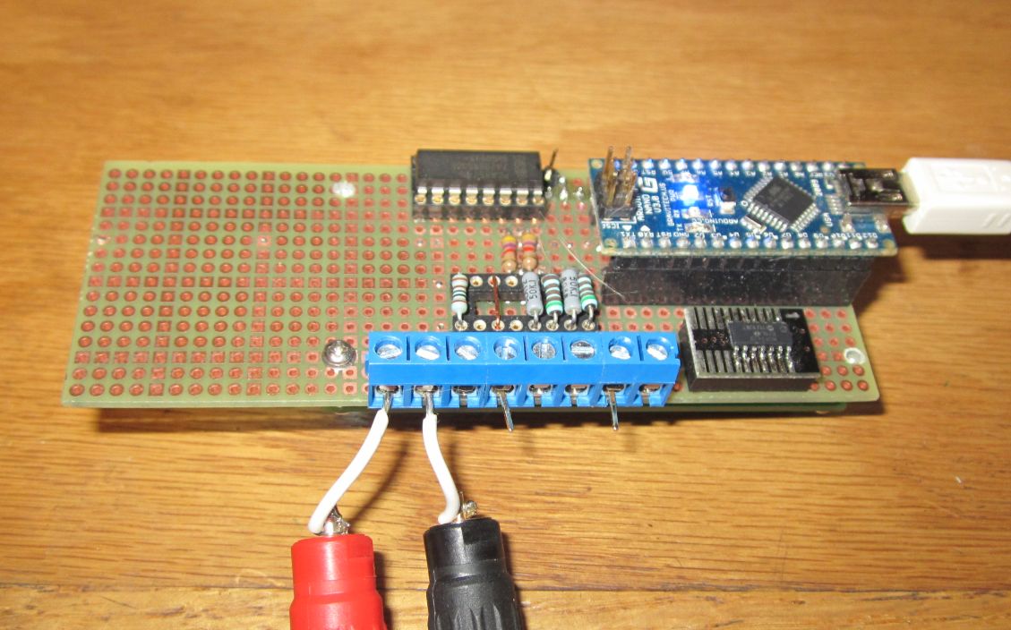
With a small amount of external circuitry it can also control
external devices
The top view. The area to the right is for optional controls
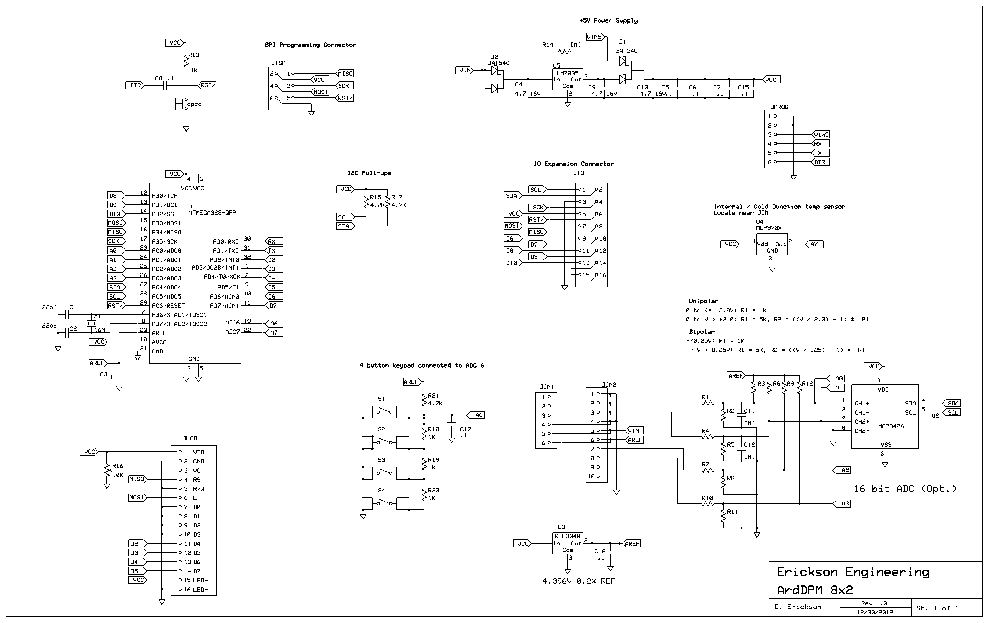
I chose to use an Arduino compatible processor. This made the
development and tools free and simple. The basic libraries for
controlling an LCD, ADC, I2C and other peripherals are there and
easy to use. The bare ATMEGA328 processor is about $1.50 in 100's
and can directly do 10 bit conversion, suitable for some
applications. I usually include provisions for a precision
voltage reference connected to the processor reference pins. This
allows any reference voltage up to about 4.5V to be used. Common
reference values are 2.00, 2.048. 2.5, and 4.096V.
But many of my application need more than 1024 counts of ADC.
After investigating low cost ADCs I found a very nice one: the
Microchip MCP34xx series of Delta-Sigma ADCs. These are available
in either 16 or 18 bits, have flexible differential inputs, I2C
interface, and an internal reference. They come in 1 to 4
input versions. They are relatively slow, but plenty fast for a
panel meter read by a human. And they can trade-off resolution vs.
conversion time. The 2 channel, 8 pin, MCP3426 is $2 qty 100.
I tested the 4 channel 16 bit part, the MCP3428 and was very
pleased with the linearity, noise level, input ranges, and easy to
use I2C interface. RMS noise was well under one count. But what
got me excited was the 8x range. This range measures +/- 256mV
full scale. Since the input voltage can be negative and as low as
-.3V, the part can measure negative voltages up to full scale,
with only a positive power supply. This is ideal for a Digital
panel meter!
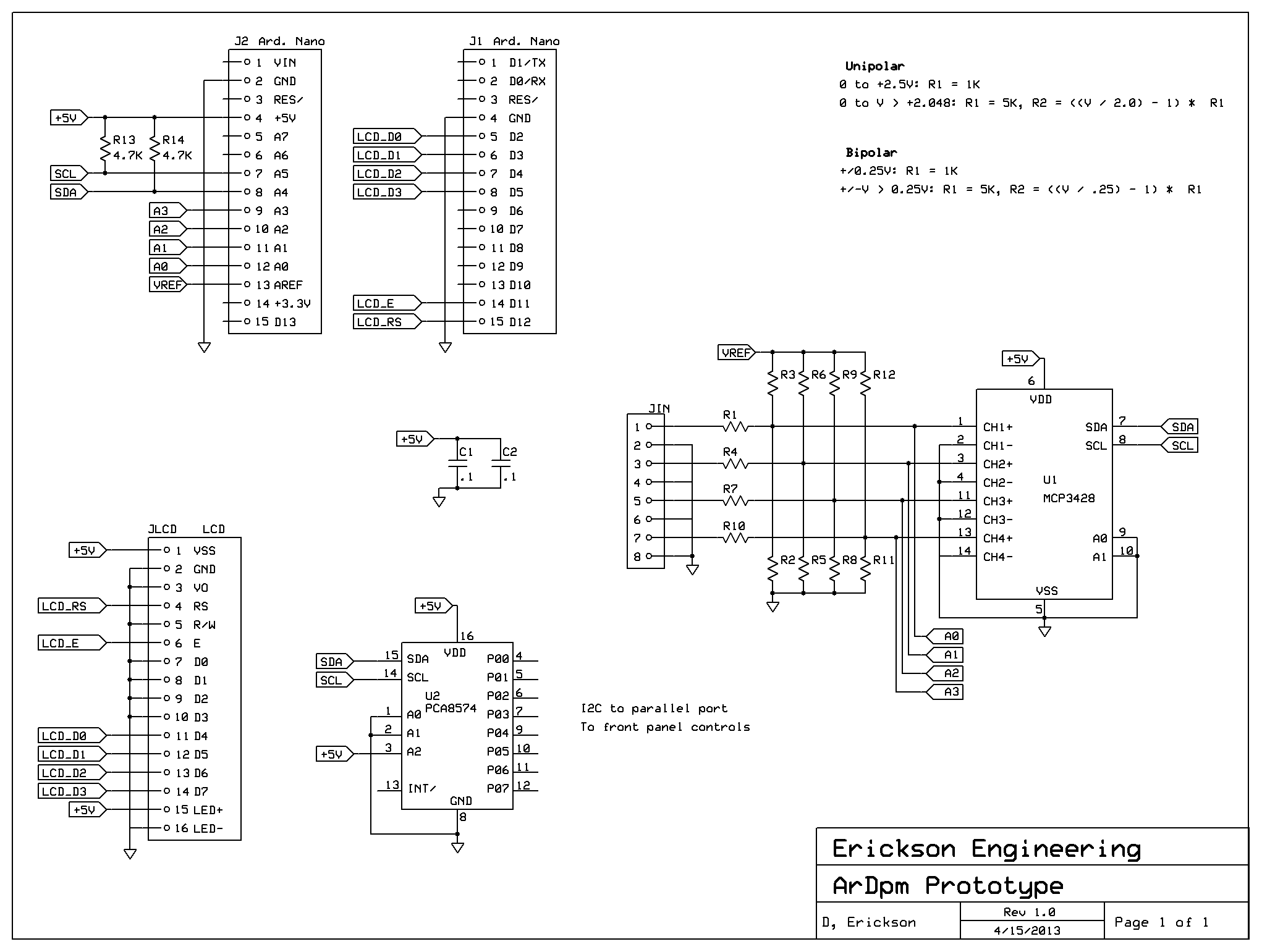
The input impedance for the 8x range is 2Meg / 8 = 250K ohms, so
it will cause a slight load on a 1-5K source impedance, But this
can be calibrated out. In a digital panel meter, resistor dividers
are often used to convert a higher input voltage to the ADC input
voltage. This approach allows the full resolution of the ADC to be
used to measure any input voltage range. So for example if you
want to measure 40V, the divider is 40V / 256V = 156.25 : 1.
Assuming a 5K resistor to ground, the top resistor is (156.25 -1)
* 5K = 776K. The total input impedance is 777K + 5K = 781K. It is
good to leave some extra input range to account for component
errors and for calibration if you want, so let's use standard
values of 4.99K and 806K for our 40V application. At 40V this
draws only 50uA from the load, suitable for higher power battery
applications.
Calibration and Accuracy
The MCP34xx parts have a good internal reference: .1% and 15ppm/ºC
gain error including the PGA and the reference. Their offset
performance is excellent: 30uV typ. and 50nV/ºC, This is due to
their auto-zero architecture. This means that for many
applications, no offset calibration will be needed. To get better
than .1% gain accuracy or to compensate for the input divider
resistor errors, you will want to do a simple gain correction.
One nice thing about Arduinos is that it is easy to make unique
code changes for a single unit. All you need is to change a FLOAT
constant, recompile, and download. This is a bit of a hack
since you are modifying the source code for each unit, but it
eliminates the need to write calibration code and manage EEPROM
values. You can do it with the built-in EEPROM, particularly if
you want to calibrate the system after installation.
Can it measure thermocouples??
Yes it can. A K-type thermocouple is about 40uV / ºC. One
count of the 16 bit ADC at the 8x range is 0.256v / 32768 = 7.8uV,
so about 0.2ºC resolution. Cool! A thermocouple needs
cold-junction compensation, but a solid-state temp sensor
connected to a spare 10 bit ADC channel on the processor can do
the job nicely. I used an MCP7900. For the thermocouple, if
you want more temperature resolution, the 18 bit MCP34xx parts can
be used.
This means that the panel meter can be the basis for a reasonable
temperature controller for an environmental chamber or IR reflow
(toaster) oven. Or any other application requiring temperatures
over 100ºC.
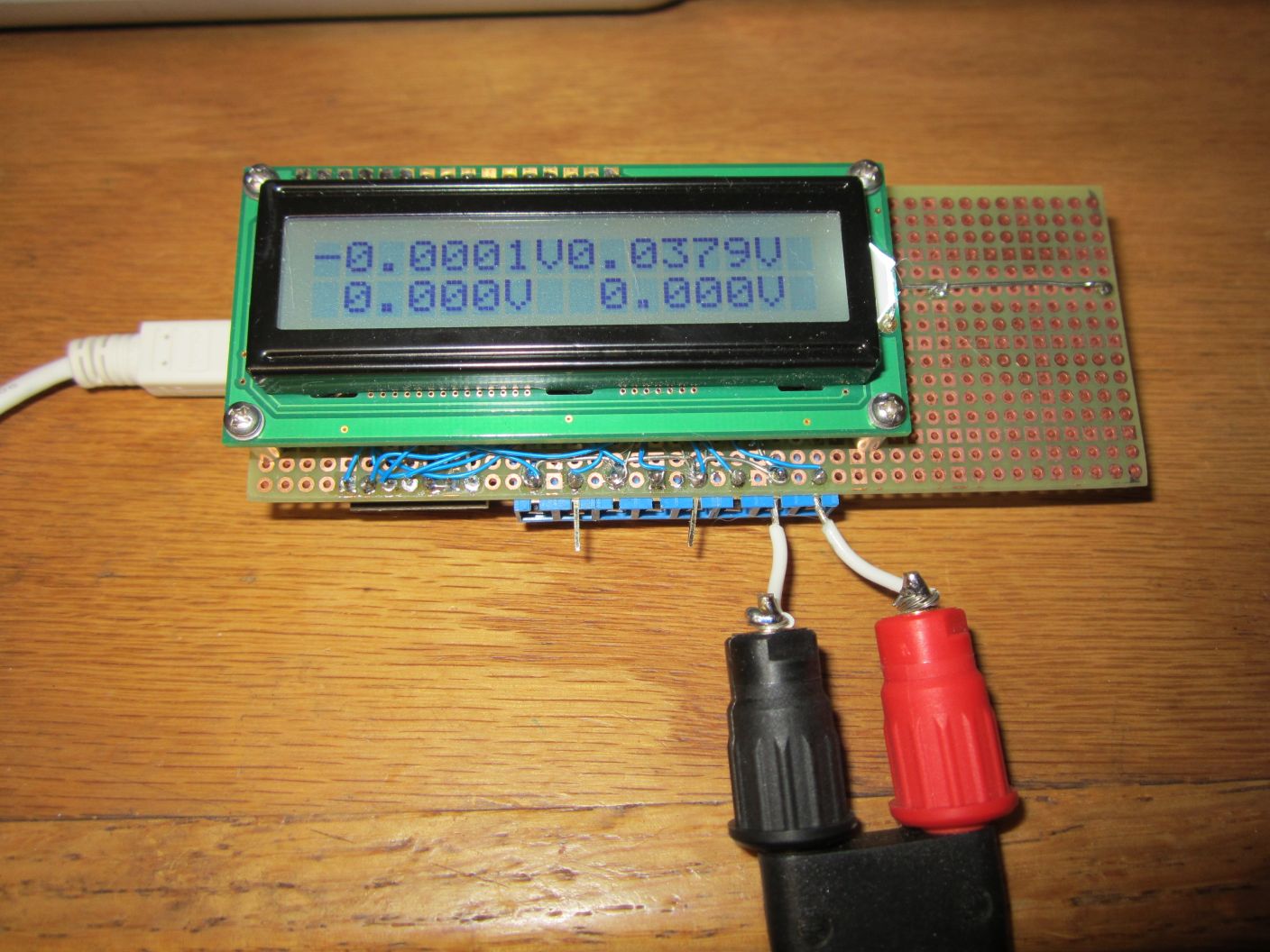
Display
My first prototype used a 16x2 row LCD. I found it was a bit
large for my projects. And 16 characters can be too many for just
displaying 4.5 digits of voltages or currents. A standard
16x2 LCD is 3.15" long. There are 8x2 LCDs that are either 1.58"
(40mm) or 2.3" (58mm) wide. 8 characters is enough to display 5
digits, sign, decimal point and units, ie. -2.3456V I
chose the 56mm versions.
A downside of using alphanumeric displays
is that the digit size can be small. You can read it from a
viewing distance of a few feet, but probably not from across
the room.
Another downside is that for a compact
design, the PC board typically driven by the display size.
This isn't much of a problem if you can find a 'standard' size
LCD. Be careful here since there can be small
manufacturer-to-manufacturer variations.
LCD Connector
Alphanumeric LCDs come without connectors. Soldering one to a
PC board is pretty simple: use a 2 row 14 pin header and solder it
to both the display and the PCB. But this means that you can never
have access to the PC board rear side behind the LCD. Since I want
a flexible platform, this would limit expansion. I looked at
various 2 row .1" thru-hole header, and most are pretty tall. My
solution s to use low-profile female pins that allow the male pins
to protrude below the surface of a board, such as Harwin H3153
(Mouser) and MillMax
0552 (Digikey). These accept 0.018" or 0.020" diameter pins,
also made by Harwin and MilMax. These allow about .15"
board-to-board spacing for about $0.18 a pin pair. If you decide
you no longer need the ability to remove the LCD, simply use a low
cost 2 pin header. If height is no object, use any .1" pins socket
combination.
The 58mm LCDs are typically 14 pins, with 2 pins at the opposite
end for the LED back-light. My idea here is to install a 16 pin
header in the 14 pin location, but cut the 2 extra pins off where
they plug into the LCD. Then run 2 wires along the back of the LCD
to pins 15 and 16 of the header to the back-light pins. The
board will therefore support both 14 and modified 16 pin LCDs.
You could of course add a second connector between the LCD
back-light pins and the board, but this seems cumbersome.