Arduino(TM) LeOLED front
panel and panel meter project
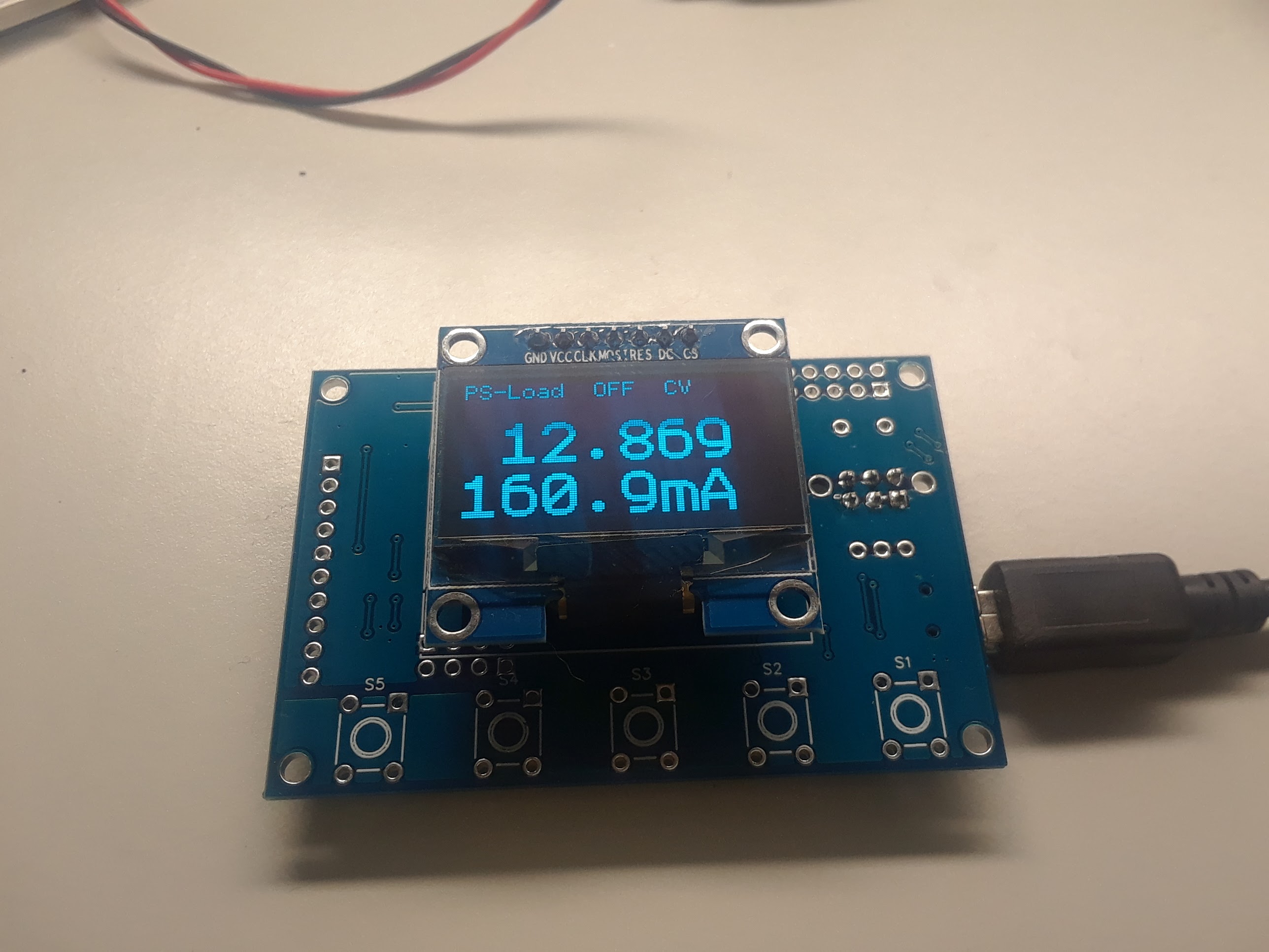
I built a basic panel meter and front panel with a 2 line LCD.
Pretty boring, eh? But add a new OLED display and this thing pops!
LeOLED is a project that addresses the need for a simple and low
cost, Arduino based front panel and panel meter. The basic features
are those of an Arduino Leonardo or Micro board, plus a small
graphics OLED display, encoder and buttons, and is designed to mount
to a front panel. It is a big step above the usual character based
LCD displays on a Shield board in terms of size, cost, and
functionality.
The optional panel meter (PM) functions provide a higher
resolution 12-16 bit ADC with 4 channels, and a precision 2 channel
DAC. These can be electrically isolated to provide electrical safety
or to eliminate danger to the PC USB ground.
LeOLED Basic Features
- 128 X 64 1.3" OLED display
- Blue or Optional white on black
background. Very high contrast.
- Fast hardware SPI interface
- ATMEGA32U4 (Leonardo) processor
- 32K Flash, 4K RAM
- Native USB Devices:
- Serial USB
- Midi USB
- Keyboard, Mouse USB
- USB Programming
- 6 Analog / Digital pins on 10 pin header
- 2 serial, 1 I2C, 2 Digital pins on 10 pin header
- U8G2 Graphics library features:
- Dozens of fonts from 5 to 32 pixels high
- Graphics primitive functions
- Fast and efficient: 1K RAM buffer, small code size
- Also supports Adafruit graphics library.
LEOLED PM Additional Features
- Isolated or Non-Isolated precision ADC and
DAC
- 4 channel precision ADC: MCP3428
- 12/14/16 bits
- 16 bits 15 SPS
- 14 bits 60 SPS
- 12 bits 240 SPS
- ADC Input voltage ranges: +/- 0.256,
0-0.512, 0-1.024, 0-2.048
- User provided input resistor dividers can
extend input voltage range up to +/- 100V
- Perfect for DC voltage and current
monitoring with external grounded current shunt resistor
- Optional 2 channel DAC, 12 bits AD5627R
- 10ppm/C 2.5V reference
- 1 LSB INL
- Optional 14 bits (AD5643) or 16 bit
(AD5663)
- 10 pin header or screw
terminals
- 4 ADC Inputs: 0-3
- 2 DAC Outputs, 0-5V
- 2 Grounds
- Isolated +5V
- I2C. One wire shares input 3
- ADC and DAC can be Isolated (300V) or
non-isolated (grounded to USB)
- Isolated I2C expansion connector for
external devices
History Lesson
I tried to design and use virtual instruments with no front panel
controls, and was reasonably happy with their GUI based controls on
a PC. But when you have a simple test to do, it can be a pain to get
a PC, install the software, connect up the instrument, run the
software.... I found that I prefer knobs and displays.
My first microprocessor projects used 2 and 4 line character
LCDs and a few buttons. Back in the 80s and early 90s we were glad
to have character LCDs. But nowadays, they are just so uninspiring.
In addition to text based displays for menus and data, I generally
needed some status LEDs. One example is a Power supply, Is the
output ON? Its it in constant Voltage or constant current.
Graphics displays are bright, and way more fun to look at. They
allow you to display any size text as well as simple or complicated
plots, graphs, and symbols.
But monochrome LCDs are also pretty uninspiring as well as
fairly big and complicated. Full color TFTs use a lot of data, and
so are even more complicated. While they are OK for a larger 32 bit
processor with more RAM and Flash, they require too much RAM and
processing for a little 8 bit Arduino.
Along came OLEDS, Organic LED graphic displays. My intro to
OLEDs was with the excellent Ornament and Crime synthesizer
module. I was impressed by the many types of displays they use
as well as the nice menu structure. In Spring of '17 I began playing
with Midi on Teensy and other Arduinos, and with OLED graphic
displays.
While I have built and used character and monochrome graphic
LCDs for many years, I often did the graphics myself, including
developing FPGAs to drive dumb graphics LCD panels. What a delight
to have an easy to use panel that is cheap and has great software
support. Here is some test code with a 128x64 1.3" OLED displaying
current and voltage plus status. I plan to adapt it to my PS-Load
system. The processor is a little 8-bit Arduino Mega32u8 board. Very
small and cool.
Electronic Load Project
This project has evolved over many years. It began when I
pulled some high power Toshiba IGBTs and large heat sinks out of the
trash at Analogic in about 2001. With a simple opamp circuit and a
0.05 ohm 25W resistor, I was able to cobble together a nice 50V, 10A
100 Watt adjustable electronic load. For a control, it used a
10-turn precision pot to adjust the reference voltage. It used a
separate multimeter to set the current, which was a problem because
you needed to actually load a supply to set the current. This
worked, but ideally you would set the current and then turn the load
ON. Additions over the years consist of a fan and fan controller,
and the first Arduino Panel Meter to read voltage and current on a 2
line LCD. I recently updated it with a LEOLED panel meter. The 0.05
ohm shunt resistor can handle 20A of current but 20A at 0.5 ohms is
20W of power. The fan and heat sink are needed to keep the resistor
at a reasonable temperature. I would operate at low duty cycles if I
wanted to run at 20A for long periods of time. And also at lower
voltages like 3-10V. At 100V I won't run it much over 1A or
100W. If I get brave and have a 100V supply that is beefy enough,
I'l try it at 2A. At 200W things get prety hot.
I use two of the 4 ADC inputs, one for current and one for
voltage. 20A at 0.05 ohms is 1.0V. The ADC has a 1.024V range so
this is the default. The ADC is 16 bits bipolar or 15 bits unipolar.
15 bits is 32,768 or about 0.61mA of resolution on a 20A range. I
display to 1mA, so no missing codes. If I want more meaurement
resolution, the 0.256V range will provide 1/4 the range or 5A max,
and at .15mA resolution, not quite one more digit of display
resolution. This will require auto range software and calibration of
the 2 different ranges.
The voltage ranging is similar. To get 100V range, I use a
1Meg / 2.5K divider and the 0.256V range. at 100V the ADC
resolution is about 3mV.
How to get started with OLEDs:
Pick up an OLED display. Buy a couple since they are cheap and you
are going to want to add them to all your projects. There are a few
choices you'll have to make:
- Resolution: 128x64 or 128x32
- Size: 1.3" or 0.96" or larger (for 128x64)
- Interface: SPI or I2C. SPI is faster, I2C
uses fewer wires. The SPI ones can usually do I2C by changing a
resistor.
- Generic (Chinese) or Adafruit
- Color: Blue or White
- Pinout: there are a few different pinouts.
I like the SPI ones with GND, VCC on the left from Ali Express
- Chip: SSD1306 or SH1106
- Software library: u8g2 or Adafruit
Install the SW library, either u8g2 or Adafruit. Un-comment
the initialization line closest to the resolution and control chip
that you have. Hardware SPI requires SCK and MOSI from your
processor, sometimes on a separate 6 pin connector. SW SPI can
use any pins but is slower to update the display. With u8g2
and hardware SPI I usethe following command:
U8G2_SH1106_128X64_NONAME_F_4W_HW_SPI u8g2(U8G2_R2, /*cs*/
10, /*dc*/ 9, /*res*/ 8);
Wire up the VCC and GND, the clock, data, and 3 control
signals (CS, DC and RES) from the initialization line you chose.
Compile and load the example code. Even without a display
connected, with a scope you should see the clock and data signals
output from your Arduino or Teensy. Once the display is connected
properly and working, you should see the demo running on your
display!
How much CPU time is used?
I measured the time to transfer the 1K buffer from the CPU
to the OLED on a Teensy and on a Mega32u4. Both use Hardware SPI
with an 8MHz clock speed. On Teensy 3.2 it took 1.6mS and on
'32u4 it tool 4mS. Not bad.
Why do I like OLEDs?
They are small.
I like the 1.3" 64x128s. These are only 1.4" wide overall, but
highly visible. They are also available 0.96", and also half
height 64x128. If they are too small for you, they are available
in larger sizes for more $$$. In the past I used 8x2 LCDs to
keep the size down, but they are very limited in what they can
display. People have made custom fonts for symbols on character
LCDs, but ugh.
They are bright and very visible.
Both Blue and White are very bright and visible. You can use
tiny fonts to display lots of stuff, or large fonts so you can
see things at a distance. The high brightness bery dark OFF
state provide a high contrast ratio that beats all but the
brightest LCDs. ????? Are they sunligh radable?
They are thin.
When building a front panel for a synth or any other project,
you need all the front panel components to be about the same
height so the controls stick through and the displays mount
behind the front panel just the right amount. This
applies to displays, pots, encoders, switches, buttons, jacks.
LEDs, etc. Add a thick back-lit LCD to the mix and you probably
blow the height budget. OLEDs are only a few mm thick. You can
mount them on any length pins or connectors to get the height
you want.
They are cheap.
Like $4-9 for a 128x64 1.3". 0.96" are a bit cheaper.
They are high resolution.
What? You call 128x64 hi-res? Yes because the pixels are tiny,
like 6-8 mils. Character LCD pixels are about 15 mils and so
look blocky. 8 mil pixels are so nice. And at that small pixel
size, you don't really need anti-aliasing.
You can add graphics and labels.
For my PS-Load project, I found myself adding LEDs as indicators
for my Character LCD projects. Not needed for OLEDs, as long as
your indicators can be all one color. There are some specialized
OLEDs with a row of yellow pixels above the blue main screen.
The intention of these is to have your annunciators in a
different color. I haven't played with these.
Flexible display.
Any size characters, tons of fonts, lines, icons, simple
graphics, small waveforms. Anywhere from 8 lines of tiny text to
2 lines of big test. You are only limited by your imagination
and code and display space.
Flexible interface.
Either I2C (fewer pins and wires, but lower performance) or SPI
(a few more pins, but fast). I2C ad SPI can be shared with other
displays or other devices. This is better than the 6 dedicated
wires on a Character LCD.
No Backlight needed
Character LCD backlights require a trimpot to adjust the
backlight and display contrast. Plus the added thickness to
spread the LED light evenly to the display. Yuk. OLEDs can be
dimmed in u8g2 with the setContrast(x) command.
Flexible Power
Monochrome OLEDs in either 0.96" or 1.3" sizes can operate from
3.3V or 5V.
Great SW support
The graphics libraries are cool, easy to use and simple. There
are two that are widely available: Adafruit and u8g2. Both are
great. I use u8g2 since it supports tons of panels, and am very
happy with it. Just a few lines of code are needed to display
many items. The libraries are small, bug-free and efficient. To
get an OLED running, just run the example code, select the
correct panel, and hook up a few wires.
Supporting multiple displays in ether I2C or SPI is pretty
simple. Just initialize 2 (or more), then write to one, then the
other. 2 or more can share a buffer, saving RAM.
Reasonable code size
32 bit processors like Teensy 3.x have gobs of code space. But
even 8 bit processors like Mega328 and Mega32U4 have enough code
space and RAM for simple apps. Watch your font selection though:
large fonts use up your code space. u8g2 has numeric-only,
upper-case-only and no-glyph versions of some fonts to save
space, so use them.
Small RAM size
The best way to use 128x64 displays (OLEDs and LCDs) is to write
your graphics to a memory buffer (only 128 x 64 / 8 = 1KB)
and then update the display by transferring the memory buffer to
the display. Mega328 and Mega32u4 only have 4K RAM, so keep this
in mind. A 320x240 TFT color LCD display with 16 bits per pixel
needs 320x240x16/8 = 153KB of frame buffer. Everything takes
longer and uses more memory.
OLED, meet Synth: The CV to Midi Project
Here is another OLED project, a CV to Midi converter. This
accepts 1V/ octave Control voltage plus a Gate signal, and
outputs Midi data to any Midi instrument. Currently it outputs
Midi to the lower left connector. It also sends Midi to a
Synthesizer-on-a-chip, the VS1053B, on a board by Adafruit, in
the upper left corner. The display shows the Note code being
output as well as the instrument being played. The two
push-buttons select the instrument. I love this thing. It allows
my various analog sequencers to play any midi synthesizer or
other instruments.
My plan it to make a real PC board for Eurorack with a handful
of trigger and CV inputs. General Midi synthesizers have plenty
of drum sounds, so I plan to use trigger inputs to control
drums. Additional CV inputs could affect the drum pitch or act
as velocity inputs to affect the the instrument velocity.
The module on the lower left is a Teensy 3.2 processor. To
process the control voltage is one op-amp. The Teensy 10 bit
on-board ADC digitizes the signal and converts it to a note. A
single transistor (to the right of the buttons) accepts the
trigger input. The DIP near the OLED is an op-amp to process the
CV input. The DIP on the right is an opto isolator
for the MIDI receiver, not used with this design. The upper
right stuff is just leftovers from the VCA project. I plan
to post the schematic, board files and code....
OLED 2 CV to Midi project
The
Blog for this project
The
Blog for this project
Back to Dave's Home Page
This page was last updated 10/18/2017