Confessions Of A
Lifelong DIY Audio Nerd

Intro
As an electronics
engineer I've always been interested in audio. I have built my own
audio equipment for many years. Speakers, Preamps, Amplifiers, you
name it, I have built them. In the early years, I was always on a
budget. Quality HiFi equipment has nearly always been outside my
reach, financially. When I was a poor high school or college
student, then a new grad, I lusted after quality audio equipment.
I set about designing, building, fixing, and copying quality
equipment. I got in the habit early on and kept it up well into
retirement. At first it was a necessity, but it soon evolved into
a great hobby.
Back in the sixties, I collected junked tube radios, shortwave
radios and record players. My parents had an old RCA record player
with maybe 10 albums. Mostly Perry Como and other 50s performers
that they loved. The band that turned me on to music listening was
Herb Alpert and the Tijuana Brass. In junior high and high school
I collected old hand-me-down radios, audio equipment and parts
from the side of the road, all tube based.
In 1970, my older cousin Joe returned from Vietnam with a very
nice Sony component stereo system that he bought in Japan. He also
had a decent music collection and I would go to his house with my
three and a half inch reel-to-reel tape recorder and record some
of his albums.
In college in the mid-70s I had an old tube console record player.
I couldn't afford albums so I borrowed LPs and 8-tracks from my
friends, sister, and cousins. My sister had good taste in prog-
rock and had Jethro Tull and Yes albums, and 8-tracks. In college
I built my first real audio system, a portable boom-box. It
used some 6x9 car speakers driven by an 8-track tape deck. It was
powered by a 12V motorcycle battery. We would bring this to the
beach, on camping trips, to spring break, or whatever social
events and it was great to listen to. We called it the party box.
I wish I had a photo of it.
In college at WPI in the early 70s a few of my fellow dorm
residents had decent stereos and I learned to enjoy them. FM Radio
had finally caught on and there were some decent College stations
in Worcester and Boston that we listened to. That was the end of
AM radio and Top 40 for me.
When I started my first real job at Hewlett-Packard Medical in
Waltham, my first roommate had a nice stereo that I listened to.
After 1 year I needed a new apartment and moved in with my current
wife as roommates. I asked if she had a stereo and she said no,
but she had an awesome record collection, so I was motivated to
get a stereo going. I started with a junky receiver that I bought
for $10. We used it at work to listen to FM and had a rudimentary
headphone Network wired into the building so you could plug in a
pair of headphones with a volume control to listen to it. When I
brought it home though, the phono preamp was not working. I traced
the problem to bad electrolytic capacitors in the phono preamp
section. But when I replaced one of the bad capacitors, the volume
increased slightly but it was still very low on that channel. I
soon realized that all the capacitors in the phono preamps were
bad and so replaced them all in both channels. I forgot what I was
using for speakers and a turntable but I'm sure there was
something I scrounged up for almost free. finally Alex and I could
listen to her album collection.
DIY Bose 901s
Then one day at work I
learned that some of my predecessors had built Bose 901 speaker
clones. I asked for the plans for the enclosures and the
equalizers and they showed up on my desk. I looked them over and
realized that building the speakers and the equalizers could be
done fairly cheaply. I asked around to see if anyone else was
interested in such a project and sure enough 10 people signed up.
I end up making 12 pairs of the Bose 901 clones and equalizers. I
volunteered my dad, a carpenter, to build the cabinets. He along
with my friend Dave cranked them out over a few weekends.
For the equalizer PCBs, I enrolled one of the guys in the PCB
department at Hewlett Packard. I laid out the single-sided PCB and
he built 12 bare boards. All of the components were in
Hewlett-Packard stock and HP had an arrangement that employees
could buy components from stock at their Cost Plus 10%. I remember
that the components cost about $12 per equalizer. Everyone built
their own circuit boards. I ordered 12 * 18 = 216 of the 4.5 inch
speaker drivers, 4 1/2SR10B from CTS. A week or so later an entire
pallet of drivers was delivered to my desk at HP. I built up the
first set and they worked really well. I distributed all the parts
and cases to all the other builders. everybody was happy with what
we built. I personally listened to them for about 25 years. Here
is one of the first Bose Equalizer boards, installed in my first
DIY preamp.

Advent 300 Receiver

I bought an Advent Model 300 receiver to use as a preamp. It only
has 30 watts per Channel which is not adequate to drive Bose 901s.
My intention was to use it as a preamp and to drive a equalizer
and an external power amplifier for the Bose 901s. The Advent 300
has a state-of-the-art audiophile phono preamp design by Holman,
similar to the one in the Apt Holman preamp. Unlike many 2
transistor Phono preamp designs, this one used a proper transistor
amplifier and achieved low noise and better than 0.01% distortion.
But when I brought the receiver home and connected it to
the speakers, I discovered that there was a fairly loud hiss. I
could hear the noise with headphones and speakers. At first I
thought maybe it was only my unit, so I went back to the store
with my headphones and plugged them into the store demo unit, and
sure enough it had the same noise. I traced the noise to the tone
control section of the preamp. I noticed that the volume control
was before the tone control section, not after. Typically this is
bad practice because any noise generated in the tone control
section feeds your amplifier directly at full gain, and so can be
audible. The noise was pretty bad with the built-in 30
watt-per-channel amplifier and even worse when feeding an external
high power amplifier. So after thinking about this for a while, I
rewired the volume control in (my precious) A300 receiver, to move
it after the amplifier preamp stage and before the amplifier. At
least at quiet volume levels, the noise was reduced significantly
by the volume control. Important lesson learned. My intention was
that I would use The A300 as a preamp and would design a high
power amplifier stage to drive the Bose 901s. Note the Preamp
Out / Amp In connections on the A300 schematic below.
Here is the Advent 300 Phono preamp, Tone stage, and Amp
schematic. Note the volume control located just before the
tone section. I rewired mine to place it after the tone control
and before the amp. I also "borrowed" their excellent low-noise
Holman-designed phono preamp circuit and built several of these
boards over the years.

BPA and Preamp
Bose 901s are some of the
least efficient speakers ever made. Each speaker uses 9 identical
4.5" drivers, which are good midrange speakers. To compensate for
the low response at low and high frequencies, an active equalizer
is used to boost highs and lows considerably. The active equalizer
has up to 14 dB of bass and treble boost to compensate for the
driver frequency response so to get 1 watt of sound out of the
speakers requires about 25 watts of power. The minimum recommended
amplifier is 100 Watts but 200 to 300 watts is preferred.
At Hewlett-Packard in the 70s, I worked with some pretty great
engineers. Two of our EEs were Mel Clarke and Rich McMorrow, who
founded Dunlap Clarke. Dunlap Clarke built the Dreadnaught 500 and
1000 Watt high power amplifiers for dance clubs in Boston and
everywhere else, and for crazy audiophiles. Mel was a great guy
who I got to hang out with on a number of occasions. Inspired by
Mel and Rich's amazing design, I thought I would give it a try. I
aimed for a reasonable 100 Watts per channel into 8 ohms to drive
a pair of Bose 901s. This was my first high power amplifier design
and I used components that were available from Hewlett-Packard
stock. For heat sinks I pulled some dual TO-3 heat sinks from a
scrap bin. For a transformer, I needed 52 Volt center-tap at 6A,
and the transformer shop at Hewlett-Packard Waltham made two of
them for me even though it was for a home project. I remember
bringing the new transformers home to my apartment in Brookline
where I tested them with a voltmeter and they measured 52 volts. I
was a bit disappointed that they measured exactly 52 volts because
I thought that the voltage would drop below 52 volts when I put a
full 6A load on them. I didn't have much test equipment in my
apartment, just my analog meter. So I loaded it with my toaster,
and sure enough the voltage did not drop. Nor did the transformer
even get warm. These transformers were really well built. I built
up the first amplifier. Ran it with full power sine waves, and
discovered that despite the load resistors getting very hot, the
transformer, capacitors, diode bridge, output transistors and heat
sinks all ran cool. I had designed it to drive 100 watt sine waves
continuously. Because real music is nowhere near the crest factor
of a sine wave, this thing was massively over-designed. I decided
that using the same power supply components and heat sinks, I
could double the number of amplifier boards and output
transistors, and run the amplifier in bridged mode to get well
over 200 Watts into 8 ohms. I built up an amplifier and it drove
the Bose 901s quite nicely. Meanwhile my friend Dave had built up
two pairs of '901s and was interested in the amplifiers so that he
could run parties in the basement of his dorm at U-Mass Amherst.
Here is my current BPA in all it's dusty 1970's glory. It has
worked well as my main amplifier for these 45 years. The beer-can
size capacitors still are fine.


When I finally changed my main speakers from Bose 901s to my new
tower speakers in 2005, I could hear a low-level hum when the
output should be silent, and some distortion when listening at
very low volumes. Finally I had efficient speakers and some of the
long-standing amplifier limitations could be heard. The hum was
caused by using cheap RCA cables which let AC in thru their
inadequate shielding. The distortion was amplifier crossover
distortion. The original design did not have a bias adjust, and
was running with little or no bias, pretty much Class B. I added a
temperature compensated bias adjust, set the bias current to about
50mA, and that took care of the crossover distortion. I ran the
gain of the amplifier at the original 51x (34.3dB) for a while
just recently in 2023 I reduced R5 and R4 to 30K, so the gain t to
about 30x (26dB). Works and sounds swell.
Preamp
In 1978 my system then
consisted of the Advent 300 receiver driving one of my BPAs and
the Bose 901 speakers. Sadly some teenage thugs from my
neighborhood broke into my apartment and stole my Advent receiver
and DIY power amplifier. I needed a new amplifier and a
proper preamp for these speakers. I liked the Holman phono preamp
design in the Advent 300, and had the schematic for it. I
laid out a circuit board to build my own. I also designed a simple
Bass/Mid/Treble tone control circuit.

Disco System
My friend Dave and I
built up a disco mixer consisting of two of these phono preamp
boards, a mixer, tone controls, and the ability to drive two of
the BPA amplifiers. For parties he would use two turntables, the
mixer, and two BPA amplifiers driving four Bose 901 clones. The
system sounded awesome and his parties soon developed quite a good
a reputation at UMass. A single large MDF box contained a two
channel bridged BPA and a second non-bridged BPA. We needed a
bullet-proof heat sink for the 8+4 TO-3 output transistors. We
bought a surplus flow-through style, air-cooled 16 TO-3 heat sink
that used a 5.25" cooling fan. This thing was a serious beast that
we found at Eli Hefron's electronics surplus store near MIT. I
wish I could find a photo of one.
Home Preamp
I needed a new home
preamp to replace the stolen Advent 300. I planned to use one of
the Holman Phono Preamp boards. The enclosure would also house a
Bose Equalizer. These were the days of cassette tapes so it needed
a tape recorder output. For input source selection in my home
system, I decided to use CMOS switches instead of mechanical
rotary switches, and instead of just using the single source
control to drive the tape output like most commercial stereos, it
would be handy to have a second source control so that I could
listen to one source while I was taping something else. I designed
a buffered input section that could drive '4051 8:1 CMOS switches.
These were driven by keyboard encoder ICs, 74C922. The switches
would be momentary and illuminated. I found some surplus switches
to use.
There is a simple trick to obtaining low distortion and crosstalk
using CMOS switches: Drive them with a low impedance, and receive
the output with a high impedance. Each CMOS switch fed into
a high input impedance buffer. In this way, the CMOS switches had
very low currents running through them, so any non-linearity in
the CMOS switch resistance was mitigated, and very low distortion
of about .01% could be achieved. Crosstalk is roughly the ratio of
the switch off impedance divided by the switch on Resistance. The
off impedance is mostly capacitive, and so crosstalk is slightly
higher at high frequencies.
I used this preamp for the late 70s, 80s and 90s until I moved
into my own house and decided that I wanted a whole house audio
system.
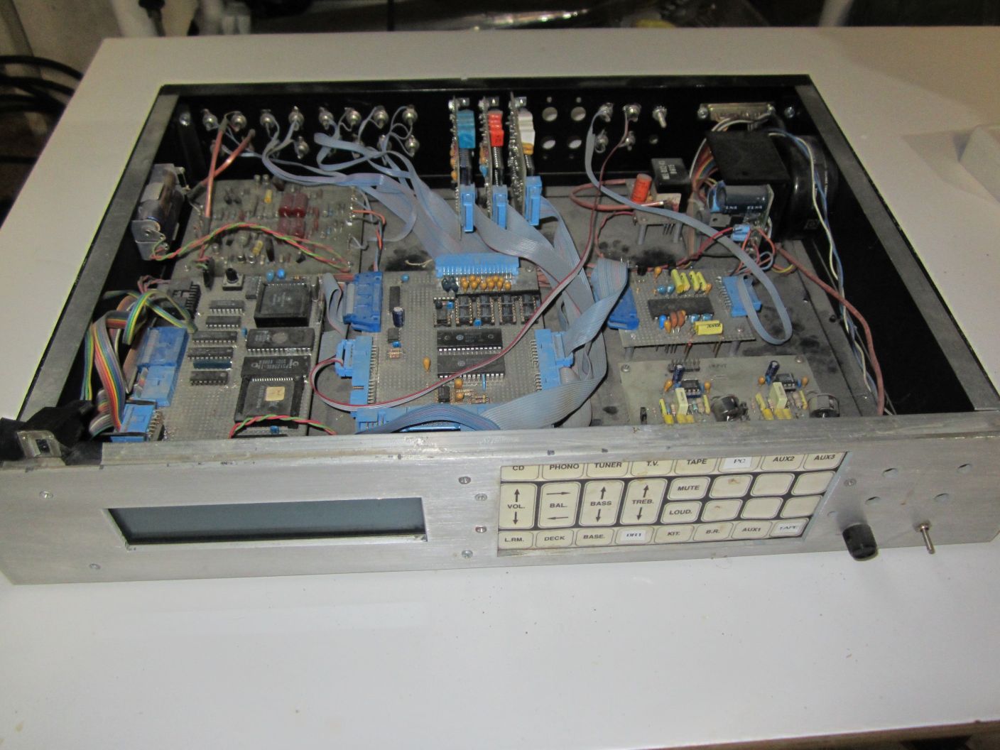
Whole House Audio
System #1
In the early 90's I
built my first Whole House audio system. It used a TDA7318 preamp
chip per-channel, and two MT8809 8 x 8 CMOS crosspoint chips,
controlled by an MC68hc11 microprocessor and a graphics LCD. Since
I had successfully designed an 8x2 stereo matrix switch on the
previous preamp, I felt confident to expand it to an 8x8 stereo
CMOS crosspoint for the new system.
- 8 x 8 stereo
crosspoint: 8 input channels and 8 zones: two MT8809 chips.
- A preamp per zone
using TDA7318 preamp chips with volume, tone, balance, etc.
- Control via front
panel, Serial port, IR remote, and wired-remote button boxes
for each zone
- LCD display: 240 x
64 surplus, monochrome graphics display to show the status of
it all
- High quality audio:
about .01% distortion, low noise and crosstalk, lots of TL084
op-amps
- High quality Holman
phono preamp
- Line level outputs
to drive external amps, powered speakers, line-in of stereos,
PCs, etc.
- Powered by a
Motorola 68hc11 processor with external RAM and EPROM
- Monochrome graphics
LCD was driven by a custom Actel FPGA I designed
The CPU (left front) and
crosspoint (center-front) boards were wire-wrapped by hand. The
main preamp board was wire-wrapped (right-middle). The other
channel preamps were small, home-etched single-sided PCBs, one per
zone. These were mounted to the rear panel on their RCA
output jacks. The phono preamp (top left) is one of my Holman
boards.
I redesigned the Bose Equalizer (bottom, right) to make it smaller
than the original transistor design board. I used NE5532 op-amps
instead of transistors (right front). For the main channel
amplifier I used my beloved BPA. For the other channels around the
house, I used a motley assortment of external amplifiers,
collected over the years, and stacked in the basement.
For firmware, I had developed a few small projects using the
Motorola 68HC11 processor with LCD graphics, and
written using the Motorola "Small C" Compiler. Which was
downloaded from their BBS. Ah, the good old days. I would
download the code to the Motorola "Buffalo Monitor" during
development, and then burn an EPROM. The LCD controller was an
Actel FPGA that I designed. For a while in the early 90s, I had a
small business building monochrome LCD controllers.
Here is the original system, now dusty and neglected. I used this
system from the late 80's until 2010 when I redesigned it.
Bose 901 Equalizer
Redesign
My first Bose Equalizer
clone was an electrical copy of the original Bose 901 Series 1
Equalizer from the 70's. I wanted to redesign it to shrink the
board size and to change the required power supply from +18V
unregulated to +/- 12V. The original design was often
coupled directly to a high-power amplifier and caused a huge 9V
step !?! to be applied to the power amplifier input on power-on.
The original design consisted of a simple transistor
voltage-follower and a simple transistor gain stage with
frequency-determining components. I felt that low-noise audio
op-amps should do the job. Here is my redesign. The frequency
determining components are the same as the original Bose design.
I was happy with the performance of this new circuit.
Here is the original Bose 901 Series I Equalizer schematic
circuit I used to build the first batch of equalizer boards. In
the late 80s, in my redesigned version, below, I replaced the
transistors with modern op-amps. The 2 transistor darlington
input buffer was replaced with an NE5532 follower. The 3
transistor discrete amplifier was replaced by another NE5532 in
an inverting configuration. I replaced the treble contour rotary
switch and its resistors with a potentiometer. The 14 pin
connectors for the input and output are what I used for power
and for connection between the crosspoint and the preamp
boards. The power supply components were optional, so the
board could be used stand-alone in a separate enclosure.


1990 Radio Electronics
THD Tester
In the early 90's I
found an article in Radio
Electronics on an THD distortion analyzer. I ordered the
PCB and front panel, and built it. It uses a light-bulb
stabilized 1KHz oscillator, and a notch filter. Decent little
design, it goes down to about 0.01% distortion or so. How about
that little NLS Miniscope!
Here is a great video
from Bettina Neumryr who also built one, and very
recently. Her excellent Youtube channel is about building old
magazine article projects.

1998-2002: Analogic
T&M
From '98 to '02 I was
Chief Engineer of the Analogic T&M division. There I helped
address manufacturing issues on mixed signal boards for
state-of-the-art ATE systems.I worked on the Credence HF (High
frequency) and LF products. The LF was an audio frequency test
system with performance comparable to Audio Precision systems at
that time.The LFAWG was an arbitrary waveform generator. In
addition to the fast and precision memory / DAC system, it used
two stages of low-distortion, programmable band-pass filters to
improve the SNR and distortion specs of sine waves. The LFACP
digitizer used programmable notch filters to perform the same
improvements on measured signal. Some techniques that these
products used were:
- Many composite
op-amps (Precision stage followed by fast, high current stage)
to increase BW and accuracy.
- Most amplifier
stages were inverting, to reduce CMRR issues.
- Metal foil resistor
networks for precision and low distortion (low voltage and
power variation)
- Many latching relays
to control coarse gain stages. Latching to minimize thermal
effects.
- Programmable notch
and bandpass filters: State-variable, using AD797s and
AD7533 DACs
- Separate +/- 15V
regulators for critical stages, to provide clean power, reduce
power crosstalk, and improve PSRR
- Power provided by
isolated +/- 17V supplies. These were driven by an isolated,
remote, differential, 100KHz sine-wave power source.
- Bootstrapped buffer
for the LFACP front-end: Very high impedance, differential,
outstanding CMRR.
- Coaxial pogo pins to
connect to the DUT boards.
- The lab at Analogic
where these products were produced contained 3 Credence ATE
test systems and was climate controlled to +/- 1C.
All in all it was great
experience working on state-of-the-art, mixed-signal products,
and learning a thing or two about high-end audio test.
The LF products were
designed and produced by Analogic. The HF products (4 channel,
500MHz, 12 bit digitizers and fast waveform generators) were
designed by Credence (formerly Tektronix) and manufactured by us
at Analogic. They used Tektronix oscilloscope technology,
particularly 1990's Tek TDS11401 M377 front ends
and sampling ADC technology. Lots of ICs from MaxIm, and hybrids
from MaxTek, both Tek owned at the time.
New Tower Speakers
In 2005 I upgraded my
1977 DIY Bose 901 speakers. Here is the Tower Speakers project page.
PC Preamp: PC audio
interface
In
2008 I decided to build a PC
Preamp. It would interface between a PC that used for music
listening, and the rest of my whole-house audio system. It has
volume and analog tone controls, source selector, a Phono Preamp
for ripping LPs to .MP3, and audio transformers to provide
isolated audio to and from the Whole-house system.
Whole House Audio
System #2
In 2010 I wanted to improve my coding skills, and get into a new
processor. So when the opportunity to enter the STM32 Challenge
appeared in December '10, I decided to do it. Winter is a perfect
time to do nerd projects. So what to design? I wanted to do
something with both nerd and general appeal, something that I was
familiar with and could use myself. My original house-wide home
stereo was showing its age. The parts and technologies I used for
the original 1990 system were mostly obsolete. The 68hc11
microprocessor, LCD, FPGA, preamps, and other key technologies had
gone end-of-life. I wanted to update this system to newer
technology and new PCB designs using ExpressPCB. Here is the page
for the new Whole
House Audio System.
2013-2016 Synthesizer
projects
More audio projects, this
time from the sound creation point of view. In 2013 I dove into
building a music
synthesizer. Fun projects, and I learned a lot.
Built a handful of custom eurorack modules: VCO, ADSR, VCA,
sequencers.
Built a handful of modules from kits and boards: 2 VCFs,
MIDI->CV, Turing Machine, Mixers.
Cloned a handful of Mutable Instruments modules from bare boards:
Braids, Elements, Ripples.
I built 2 Hammond Organ simulators based on Teensy Audio.
Then I tried my hand at building a modern Prophet-5-like
polysynth.
Built a Mutable Ambika
mixed digital / analog Polysynth.
2022 Music Server
Project
I wanted a convenient way
to play digital music through the Whole House system without
requiring a full PC. And one that could be controlled by a phone
or tablet. In 2022 I built a Rasbberry Pi based Volumio Music server.
Fun project.
Board Construction
Techniques
In the 70s, the early BPA
amplifier boards were built in my basement using hand-taped
artwork at 2:1, photo negatives made by a local print shop, and
photo-resist boards, which were then hand etched. These worked
quite well. I built several of the Holman Phono preamp boards this
way as well. The other boards in my early preamps and mixers were
mostly hand-wired and wire-wrapped since they were one-offs. That
too worked well.
Later, I tried my hand at toner-resist boards and used them for
the first Whole-House system. But the quality of these boards was
never great. I couldn't get the toner to deposit cleanly on the
boards. So I reverted to hand-wired and wire-wrapped boards for a
while. The original Whole-House system was built with a mix of
wire-wrapped, and hand etched boards. Then in about 2004,
ExpressPCB arrived on the scene. I built many, many of their Mini
Boards: $70 for 3 boards, 3.8" x 2.5". They do larger boards for a
higher price. My early synthesizer boards and the second
Whole-House system was built with these. The good part about
ExpressPCB is that their CAD tools are extremely easy to use and
their boards show up in 3 days. The downside is that it once
you design a schematic and board with their proprietary CAD
software, you are pretty much stuck ordering boards from them.
But now the Chinese offer much lower price boards. Now I use
Diptrace to lay out boards, and PCBWay in China for quality, low
cost boards.
Dave's Home Page
Last Updated: 6/2025