E-Load Electronic load. The project that will not end....
Adjustable DC Load
To test power supplies, a load of some kind is needed. This can be
as simple as a handful of different value power resistors. The gold
anodized power resistors made by Dale and others work great. These
can be screwed to an aluminum plate or other heat sink to keep their
temperatures low. I keep some 1.0, 5.0 and 10.0 ohm, 10W and 25W
values around. Put enough of these in series and parallel and you
can load down a power supply. But I never have the exact right
values and changing the load usually involved soldering. So I built
an electronic load. This load applies a constant current to a power
supply of between 3V and 30V. My original one used a simple power
N-FET bolted to a big heat sink, an op-amp, shunt resistor and
voltage reference. It was self powered from 20V down to about 5V and
designed for up to 4A loads. Over the years it was upgraded to 10A
and then 20A. Now I use a surplus IGBT which will dissipate 10A at
12V or more (120W) with impunity. I think it's rated to switch 75A
at 400V. At 120W or more, a fan is a must. The basic circuit is
quite simple. Build the electronics on a little Radio-Shack or other
proto-board and mount it on the biggest heat sink in your junk
drawer.
Rev 1
The original big heat sink (8.5 x 3.2 x 1.2") and IGBT were pulled
out of a scrap bin at Analogic in 2001. Once I had these prizes, I
had to build an E-Load Here is the original circuit. The 1.25V
reference diode, 15K resistor, and ten-turn 10K pot develop a stable
0 to 0.5V. The single-supply op-amp and FET apply the voltage to the
0.05 ohm resistor. 0.5V across 0.05 ohms is 10A maximum. You can
parallel multiple larger resistor values if you have trouble finding
a 0.05 ohm 10W resistor. To build a 5A load, use a 0.1 ohm, 5W
resistor instead. The only trick in building this is to wire the
high current path with heavy gauge (16GA or more) wire and treat the
0.05 ohm resistor as a 4-wire device: heavy traces for the high
current path, lighter wires soldered to the leads near the body for
the voltage measure path. Here is the ExpressPCB
schematic. and the .PDF.
version. For extra credit, use the unused op-amp and a
thermistor to detect when the heat sink gets hot and turn the fan
on. The circuit as shown shouldn't be used at more than 18V or so
since the full supply can be applied to the FET gate, These are
usually rated for 20V max. By removing D3 and always using the
external 12V supply, this limitation is removed and the voltage can
go up to anything the FET can handle. Watch out for maximum power of
the FET though. And remember to de-rate the FET power at high
temperatures.
The original proto had a 10K trimpot on board with an adjustment
hole in the front. Soon it was upgraded to a nice front-panel
ten-turn10K pot.
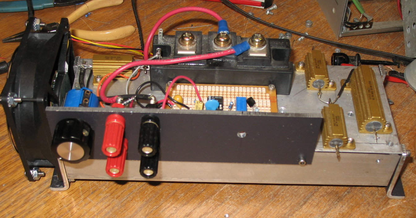
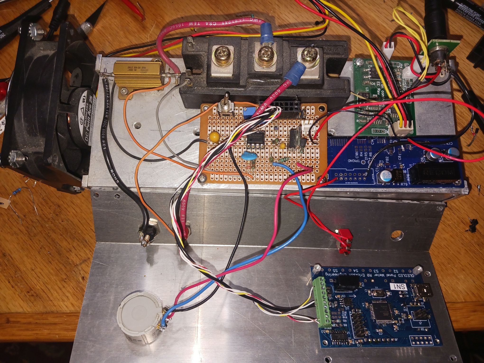
The top binding posts are for the load and the bottom ones for a
current monitor via a DMM. The 3 resistors on the right are just
spares. Note the big black IGBT in the background, this is in place
of the FET in the schematic, but a couple of high power TO-247 or
larger N-FETs in parallel will do fine. the IGBT is a half-bridge
type, with only the lower transistor used. The big aluminum
block is a surplus heat sink with its fins facing down. The steel
brackets on the end keep it somewhat thermally isolated from the
bench. I have run this beast at 24V and 10A: 240W for short periods
of time.
Here are the original specs / requirements for this version.
- Self powered or powered from the load.
- 3.0 to 30V, limited by the op-amp power supply
- 0 to 10A using a 0.05 ohm, 25W shunt resistor
- Ten-turn pot
- Use what parts I have laying around, purchase nothing!
- 100W comfortably, 200W for short periods.
- Use a big the heat sink as the chassis
- Beefy transistors or IGBT
- 12V Fan
- Uses external DMM to monitor current: 10mV/Amp
The original reason for self powering was so I could easily test 12V
batteries in the field. But a proper battery tester requires that
the load shut off below a set voltage. It also needs to keep track
of the time, in order to measure the battery Amp-hour capacity.
Also, the fan operates from the same supply, so causes ~100mA of
parasitic and un-measured current. Also a fan prefers a fixed
voltage, not some arbitrary one. Additionally, the FET really wants
about 12V-15 max, not 24V or more from the opamp. I soon decided
that self-powered wasn't such a good idea.
FET and IGBT SOA limitations in E-Loads
The power semiconductor manufacturers have recently changed how
they specify Safe Operating Area (SOA) for FETs and IGBTs. These
devices are primarily intended for switching applications, not to
dissipate hundreds of watts of continuous DC. So many parts now
only specify SOA at 10mS duration or less. Supposedly FETs can
develop hot-spots and then fail.
The part I use is an older, half-bridge IGBT module, Toshiba
MG100J2YS50. It specifies SOA up to 300W dissipation at DC,
30V @10A. 100V @2A. This thing is truly a beast.I wouldn't run it
much higher than 200W.
Back in the good old days when I first built this, FETs and IGBTs
specified their SOA at DC. Nowadays you need to buy specific
"Linear FETs" to get DC SOA curves. But for a one-off, as
long as you keep power down.... A good Linear L2 FET for a
big DC load is the IXYS
IXTN110N20 in the
beefy SOT227 package.
Another nice part I have used for high current loads is
IXFH180N20, in a TO-247, This part can handle about 150-200W
DC, but be very careful about using any thermal pads. at
150-200W, the temp rise of even the lowest thermal resistance
insulators will cause a major temperature rise. I screw them
directly to the heat sink with thermal grease, and then insulate
the entire heat sink since it is at the Drain voltage.
Inconvenient but necessary.
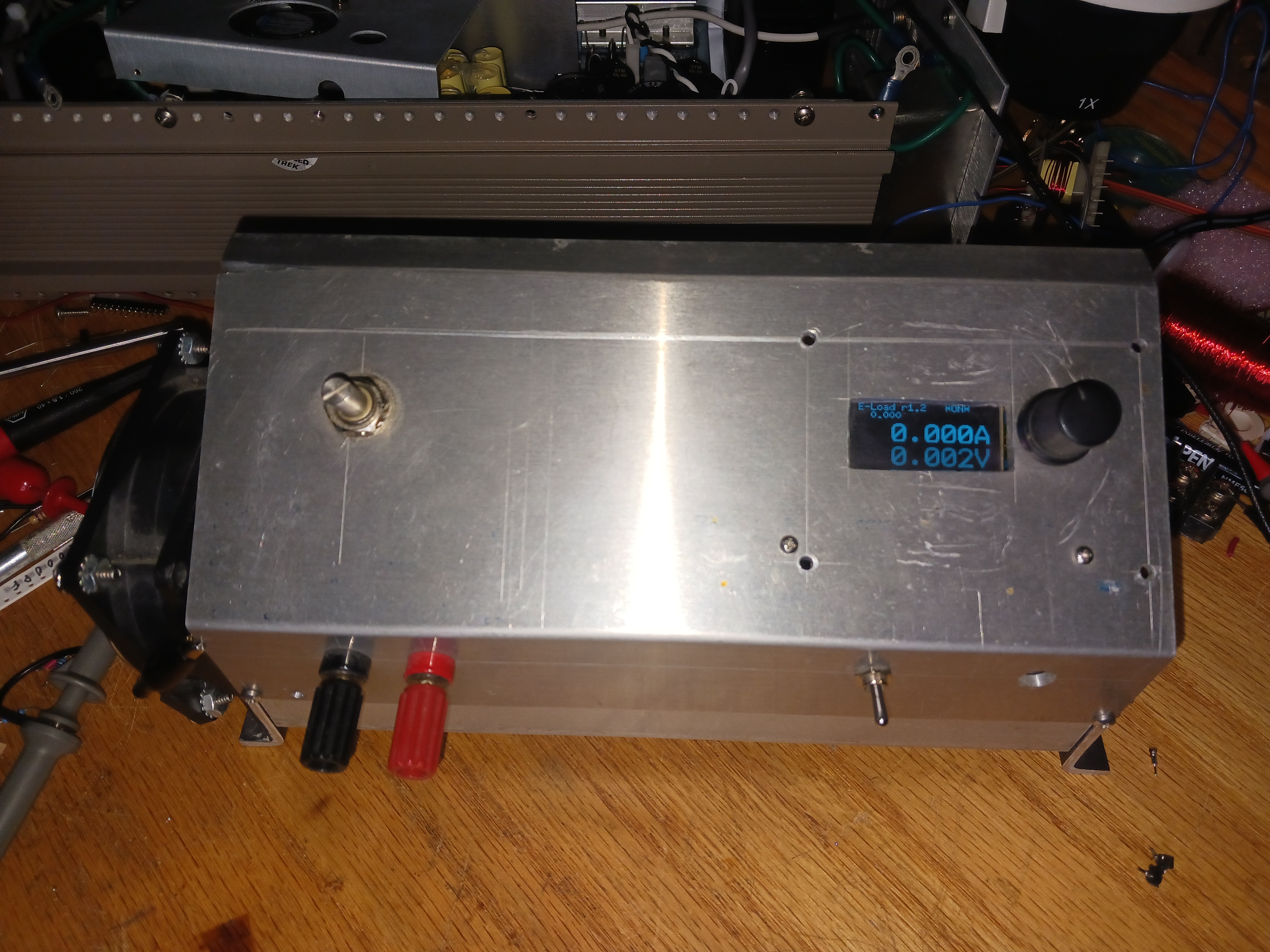
Rev 1: Digital set and display
Requiring an external DMM was inconvenient. And a voltage monitor is
also useful. Around that time, I designed LeoLed, with a 16b isolated ADC and 12 bit
DACs. It allows setting the output current precisely using an
encoder. The ADC has programmable ranges, so directly measuring the
0 to 0.5V shunt resistor was a good match. LeoLed has resistor
dividers on its inputs so directly measuring up to 100V was no
problem.
- LeoLed display
- Iset using encoder
- 15bit (16 bit bipolar) current monitor
- 0-100V voltage monitor
- Display of Iset, Imeasure, Vmeasure
- Increase current to 20A
- Increase voltage to 100V
- Separate 12V power supply input
- New slanted cover to accommodate display
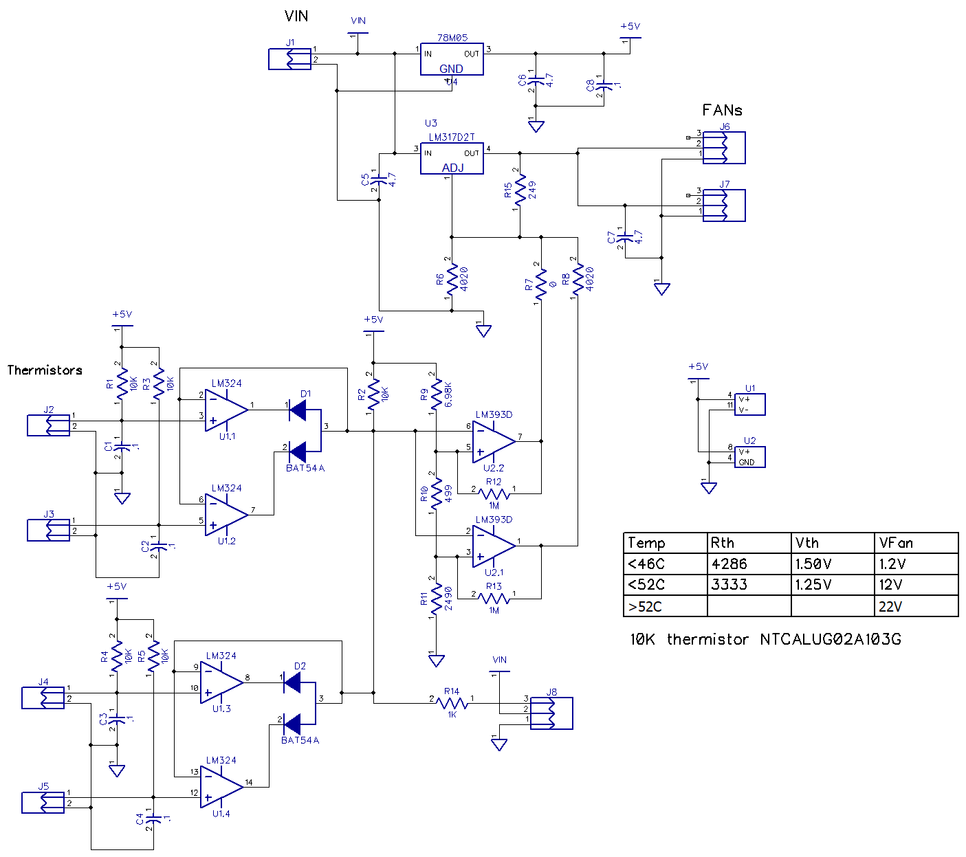
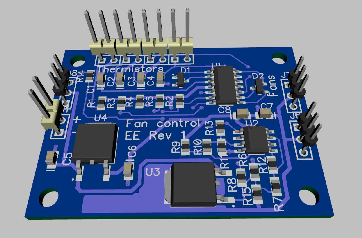
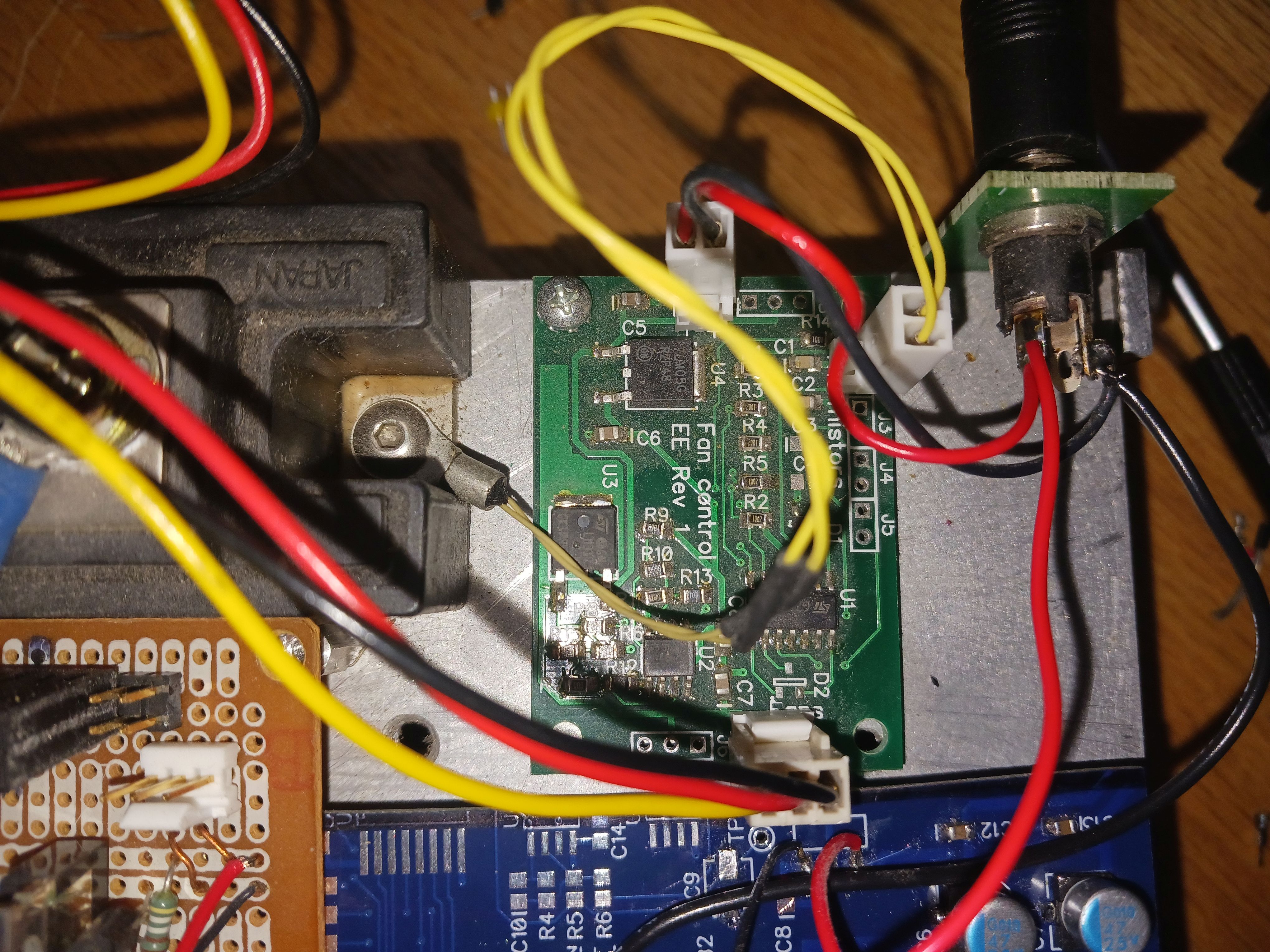
Rev 2: Variable fan control
Having the noisy fan always on is annoying. I designed a little Fan Control Board
that uses a thermistor to monitor heat sink and control the fan
speed. It has 2 fan speed settings plus OFF. It was designed for
PS--Load, but was equally applicable here. I wired the fan before
the power switch so the fan can remain on after the load is turned
off. There can be a lot of residual heat in the heat sink after the
load is removed.
Fan Board can monitor 1 to 4 thermistors and controls the fan based
on the hottest one. This circuit is for +24V input and fans. For 12V
input and fan, change R6 and R8. If you just need a single
thermistor, only use one thermistor connector and input R-C, and
U1.1, U1.2, R1, and D1 an be eliminated. J8 is if you want to
monitor the temperature.
Rev 3: DC-DC
I had planned to isolate the +12V power to the load from ground, but
hadn't gotten around to it. Without isolation, you either had to be
careful about the source grounding, or be careful about the +12V
power supply grounding. An isolated 12V AC-DC (not 3 wire AC) could
be used. Neither is good. A proper isolated DC-DC is needed. The ADC
and DAC are already isolated on the LeoLed board. That's most of the
battle.
I've done work on DC-DC
common mode noise and finally settled on the 12V to 15V DC-DC
that I use on DIY-SMU. I had spare PC boards and could easily
band-saw off the small DC-DC power section. It's the thin blue board
on the heat sink.
It is not ideal, and generates a bit of 300KHz common-mode noise.
Still working on a final solution.
Rev 4: The Future?
E-Load works well and is meeting my needs for now, but clearly some
cleanup and improvements are in order. Maybe if I get not-busy. Then
again, it works the way it is.
Maybe just the firmware updates...
- Firmware improvements:
- Fine control of current. Needs more buttons or encoder
button.
- Maybe larger OLED board. See PS-Load for possibilities.
- SCPI control over USB
- Battery test mode
- Shutoff below voltage setting
- Accumulate Amp-hours
- Single PCB containing all ??
- Maybe a second PCB for front panel. OLED and switches.
- Maybe LeoLed 2
- A better cover, maybe 4 sided.
Back to Dave's Home Page
This page was last updated 10/21/23