Lambda
LQD Power Supply Repair and Modification
The
Schematics, PCB files, and Simulation
models are
here
Introduction
The Lambda LPD and LQD lab power supplies were
extremely popular in the '80s and '90s. As a result, there are
thousands of these either in use, on shelves, or on the used
market. At Teradyne in 2007 we had a large pile of the LPD
supplies. Lambda cleverly designed them such that the same or
similar components were re-used for 1-3 channels, and from voltage
and current combinations from 10V at 5A 20V, 40V, 60V, 120V, and
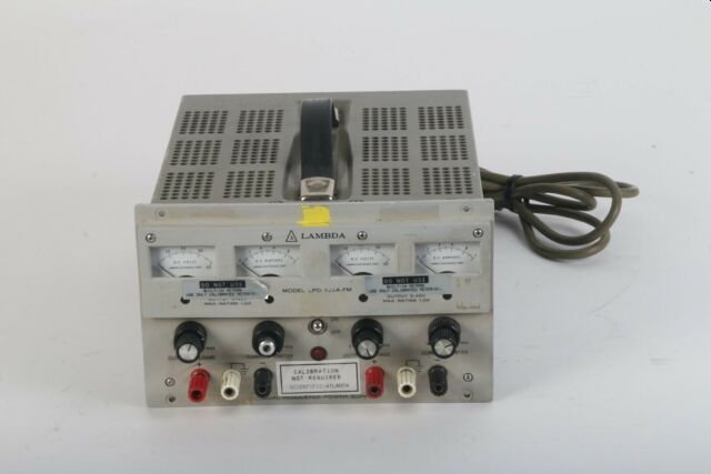
250V. The LPD was the original (beige) series which uses two
analog meters per channel, one for voltage and one for current.
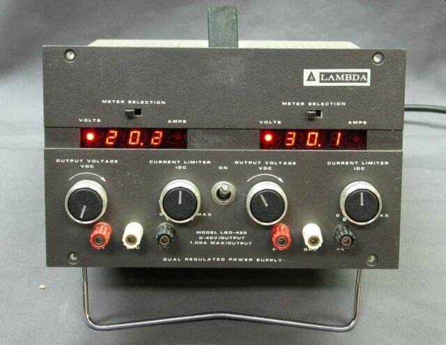
The LQD is the digital (dark grey) version, and uses a single
switchable LED digital meter for voltage and current.
These are quality power supplies, but the years have taken their
toll on them. Fortunately they are easy to work on and in most
cases easy to upgrade and repair.
Problems:
The LPD supplies have been very reliable. I had a
LPD-421A-FM, 20V 2A, 2 channel supply on my bench for many years.
I wanted the 40V, 1A digital display version, LQD-422. I bought a
broken one on Ebay figuring I would save some money, and it would
be fun to fix.
When you look at the schematics for the LPDs and LQDs, therbige
are differences. The LPD is an older all-transistor design,
and the LQD uses a proprietary Lambda control IC, FBT-00-128. The
LQD digital displays require an additional display PC board, and
require separate, isolated +/- 5V power supplies to power the
digital meter. This power supply is provided by an additional
transformer winding, diodes, filter caps and regulators on the
main board. Here are the schematics (also in the LPD and LQD service
manuals) for one channel each, of the LPD and LQD.
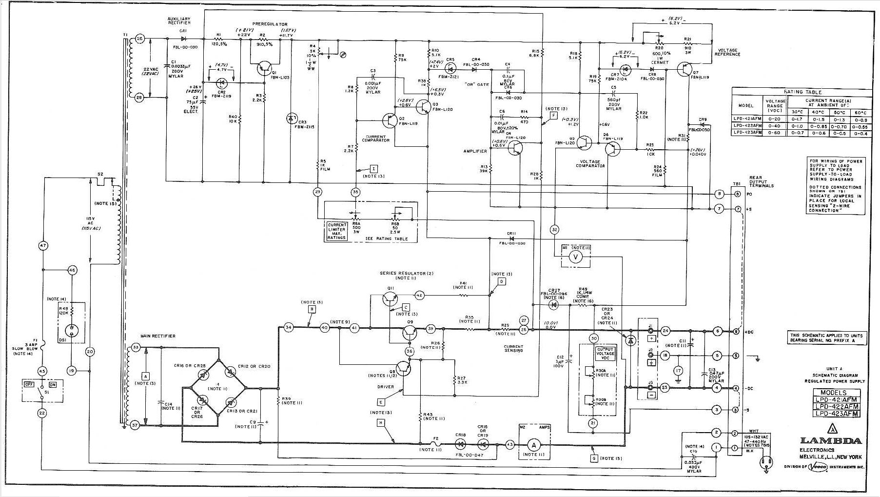
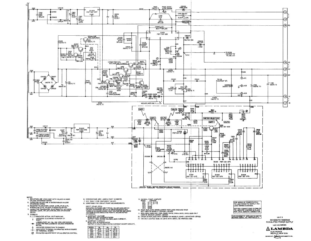
The LQD schematic shows several Lambda
proprietary part numbers for key components. Don't panic, most of
these are Lambda versions of pretty common ICs.
- IC402, FBT-00-047 is a 7812 +12V regulator
in TO-3 case
- IC403, FBT-00-045 is a 7805 +5V regulator
in TO-3 case
- IC201, FBT-00-074 is a ICL7107 A/D with LED
drive, 40 pin DIP
- IC301-303, FBT-00-075 is a 7-segment
LED. Similar to HP 5082-7731, available on Ebay
- IC401,
FBT-00-128 is the main control IC. TO-99 10
pin (round metal can)
IC401, FBT-00-128 is
Lambda proprietary. There is no substitute. You may be able to buy
one on Ebay, or pull one from a scrapped power supply.
Fortunately they are fairly reliable.
By the way, in the late 70's and 80's, Lambda was a semiconductor
provider and sold several of these power ICs, particularly
3-terminal regulators in TO-3 packages.
Models:
Here are the LQD 2 channel models:
- LQD-421: 2 channels, 0 to 20V at 1.7A
- LQD-422: 2 channels, 0
to 40V at 1.0A
- LQD-423: 2 channels, 0 to 60V at 0.7A
- LQD-424: 2 channels, 0
to 120V at 0.38A
- LQD-425: 2 channels, 0 to 250V at 0.13A
Here are the LPD 2 channel
models:
- LPD-421AFM: 2 channels, 0 to 20V at 1.7
- LPD-422AFM:
2 channels, 0 to 40V at 1.0A
- LPD-423AFM: 2 channels, 0 to 60V at 0.7A
- LPD-424AFM:
2 channels, 0 to 120V at 0.38A
- LPD-425AFM: 2 channels, 0
to 250V at 0.13A
Notice a pattern?
Troubleshooting:
I'll describe my experience repairing a LQD-422.
It had several problems which are fairly common. The two power
supplies would output correct voltages, indicating that the main
regulators were working, but the 2 digital meters did not work at
all. I removed the cover and the screws that hold one of the main
boards. The board unfolds nicely and can lay flat on the
bench. I measured the raw +5V and -5V supplies with a scope
and saw many volts of 120Hz ripple, indicating bad (open) filter
capacitors. I noticed that the filter capacitors C407, C408 and
C409 were bad and replaced them all on both channels. Some of
these capacitors had red plastic caps that had actually fallen
off. I noticed that a few other caps had already been
replaced. I replaced all the original capacitors that had red caps
with electrolytics I had laying around. Feel free to use
replacement caps with the same or higher voltage or capacitance,
the values are not critical. After replacing the caps the
digital readouts worked, but.....
Panel meter design problem:
The displays are working, kind-of. The output of
supply 1 is set to 0.0V, but the readout indicates 1.0V. Also one
segment is missing on the Tens digit of channel 2. Also one knob
broke so a substitute is installed.
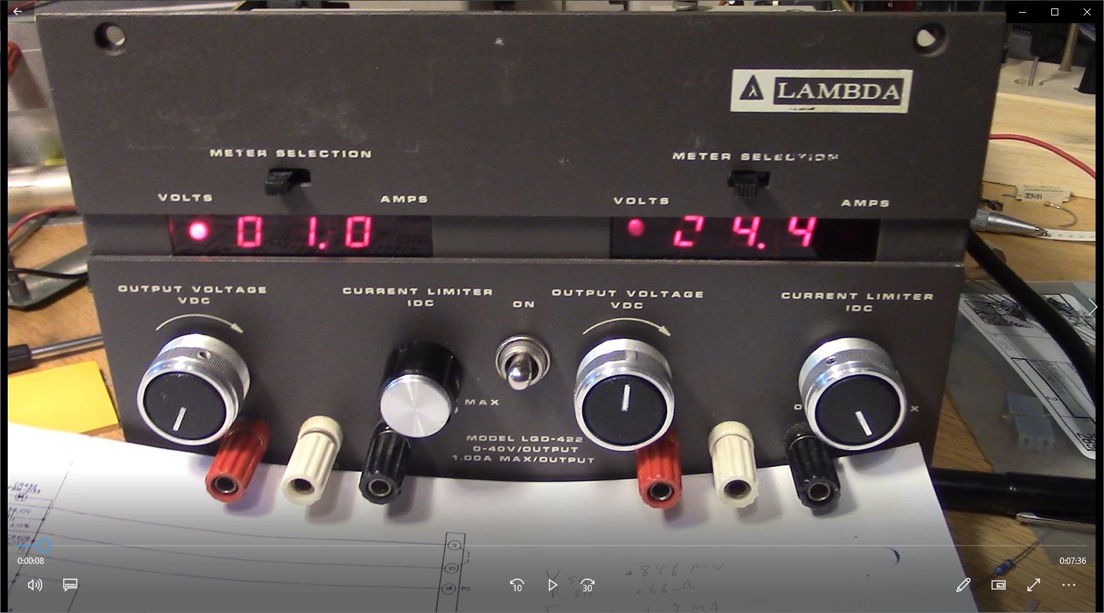
There were significant offset errors on both
channels digital meters. With the voltage set to 0.0V or the
current at 0A (no load) the meters read 8-10 counts. This is
significant since 10 current counts is 100mA, and 5 voltage counts
is 1.0V. These are big errors for any power supply.
I tried hacking in an offset trim consisting of high value
resistors to correct for the errors. It worked, but something
didn't feel right about this 'fix'. Also needed 2 or 4 trims for
the 2 meters and 2 ranges. Gross.
I looked at every photo of every LQD supply on Ebay. Some of them
had the meter switch shown in the AMPS position. And sure enough,
many showed 5 to 12 counts of offset error, just like mine!
Obviously a worldwide conspiracy.
What is the source of this offset? Good question. I measured the
input to the ADC, it was 0V. So the ADC was causing the
error. Was it the old ceramic ICL7107 chip? Was it the
board? I bought a cheap Asian panel-meter board that used the same
ICL7107. The kit that cost $8. I built it, and it worked fine, no
offset error. So I bit the bullet and un-soldered one of the 40
pin ICs from the LED board, installed a socket, and replaced the
IC with the one from the Asian board. Same offset problem. So it
isn't the input, and it isn't the chip. Then what the heck is it
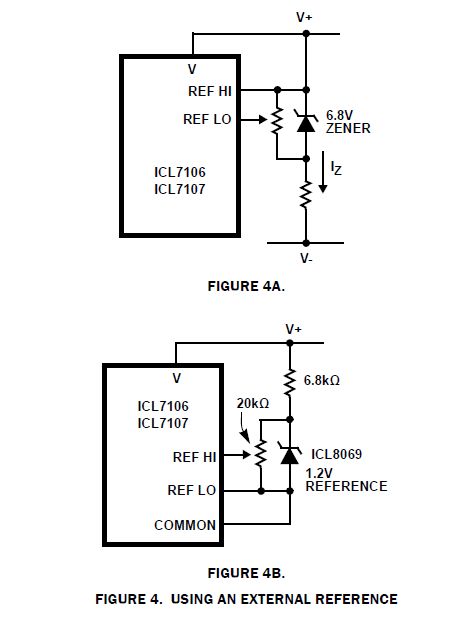
!?!. I examined the circuit for the display and the recommended
circuit for the ICL7107, and found a difference. The schematic
(above) shows pin 35, the REF LO pin connected to the +/- 5V
return, also the input return. Effectively COM for this meter
circuit. But notice the note that says -2.5V. The actual board
measures -2.5V on pin 35. So what's it gonna be, buddy!! COM or
-2.5V?
I looked at the various ICL7107 / 7106 manufacturers data sheets
for recommendations regarding the use of REF LO (pin 35) and REF
HI (pin 36). Here's what Renesas says. Notice that they show the
REF pins biased to V+, or to COM, but not V- or -2.5V.
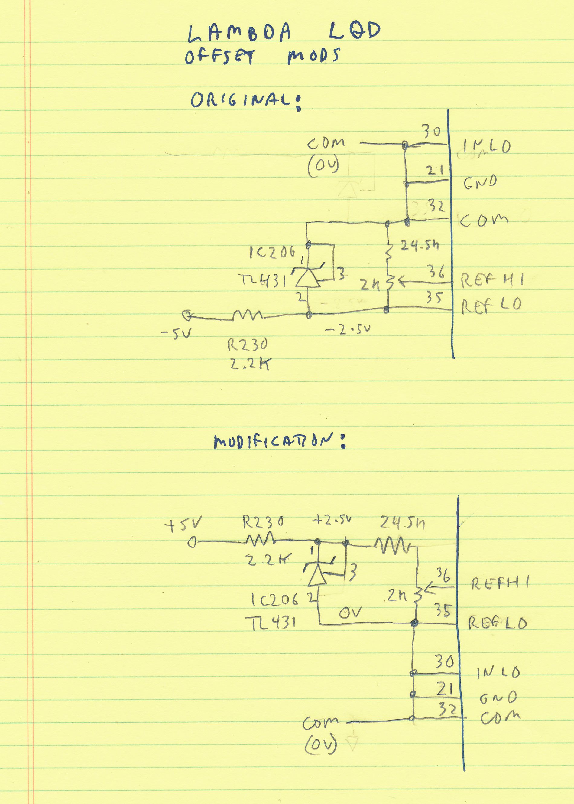
I rewired the display board to connect pin 35 to COM, similar to
FIGURE 4B, except that Lambda uses a 2.5V reference (TL431).
This took 3 cuts and 3 wires. The offset error disappeared,
Hooray! I rewired the other channel, same good results. I suspect
that Lambda fixed this problem on later units, and that the
schematic in the service manual wasn't updated correctly. I don't
have a newer unit or a newer schematic to prove this out.
Photo of rework:
Schematic of rework
While working on it, other things broke:-(
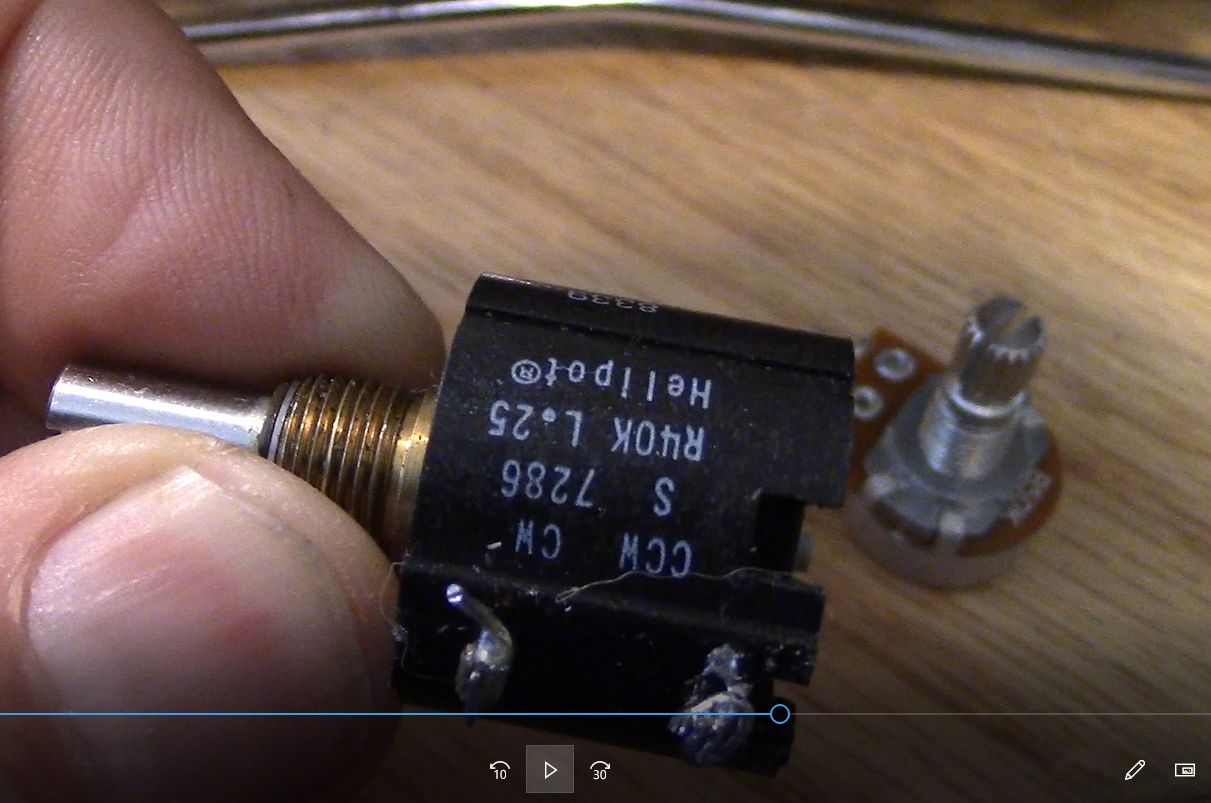
To better measure the electrolytic C35, I
un-soldered one pin of the voltage setting 10 turn potentiometer
R31. In the process, the pin broke off the pot.
Unfortunately R31 on the 40V supply is 40K ohms. On each power
supply the pot value the output voltage x 1K, so 20V is 20K, 40V
is 40K, etc. Good luck finding a 40K, 60K or 120K 10-turn
pot anywhere. I bought the closest one I could get, 50K, planning
to add a parallel resistor to bring the resistance down to 40K.
There is a place on the PC board for the parallel resistor.
I ordered and installed a 50K pot and found that the 40V supply
had enough headroom to go to 50V, even at 1A load. I measured the
raw DC and it was nearly 60V at nominal line voltage. Hey, I got
10 extra volts on one channel for free!
Notice the empty slot on the back of the old pot where the third
pin should be. So sad.
When I first operated the supply, the 7-segment LEDs were fine.
But after a while I noticed one segment was dead. I located an HP
substitute, HP
5082-7731 on Ebay and bought 5. It worked OK, but is dimmer than
the original. Lite-On makes the LTS-312AHR which looks like a good substitute.
The original 4 knobs on the LQD look nice, but they are plastic,
and two of them were cracked. The 1-turn pots on the current
ranges are hard to turn. That plus the aging plastic caused the
old knobs to crack. I added some more rugged but mismatched knobs.
I'm on the lookout for 4 matching ~1" knobs. Or not.
I also noticed that one of the status LEDs for AMPS on channel 2
was out. I replaced the LED with one I had.
Update 1/10/21
These fixes were originally made in Sept
2019. As of early 2021, this supply has been in use nearly
every day for 2.5 years with no problems.
Sad Ending 11/24
I used this supply most days until November 2024.
It worked perfectly until one day, the left channel died, with no
voltage output. The displays worked. I dug into it and checked all
the main and aux supplies. Checked all the transistors, caps
resistors and diodes. All good, no faults. I checked the
temperatures of all the parts, and sure enough the main regulator,
Lambda LAS3700, FBT-00-128 is running hot, and is outputting no
voltage or current to the pass transistors. It's dead Jim. Since
this 10 pin TO-99 is unobtanium, the power supply can't be fixed
without another IC or by replacing the left board. Choices
are:
- Scrap it and replace with another LQD-421
or 422
- Buy another broken LQD and try to get one
unit working.
- Use one channel. I need 2
- Put my LPD-421A dual 20V 2A supply back
into service.
Until I decide how to deal with the broken
supply, I put the LPD back into service. It works swell I
still like the LQD supply, and prefer it to the Chinese power
supplies out there. I hate to buy another since I'll have to
scrap one of them. I don't have space to keep another piece of
broken equipment.
Buying another LQD means I'll probably have to
fix the display offset, the knobs, and replace all the caps.
To add to the problem, these old phenolic PC
boards are tough to rework without lifting pads and traces.
Dave's Home Page
Last Updated:
11/9/2024