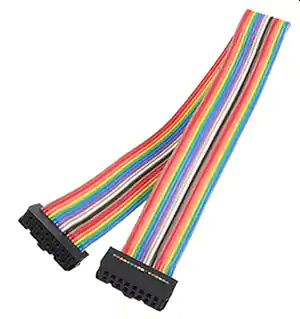
Ode to Ribbon Cables
My undying love for IDC
flat cables.
| Parameter |
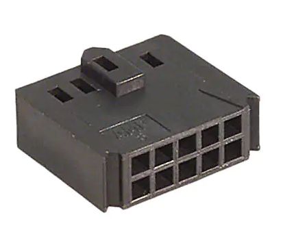
Ribbon cable |
Molex KK/ Amp MTA |
Hirose DF13 |
Flat Flexible Cables |
| Pitch |
0.050" or 1mm |
0.1" |
1.25mm |
0.5-1mm |
| Length |
Any |
Any |
Any |
Up to ~1m |
| Pin count |
6-64 |
2-12 |
2-20 |
10-60 |
| Wire size |
28AWG |
28-22 AWG |
26AWG |
.3 x .15mm copper |
| Cost / pin (parts) |
~$0.10 |
~$0.40 |
$0.20 |
|
| Cable assembly labor |
Minimal: cut cable to length and 2 press
operations |
2 crimps and 2 pokes per pin |
2 crimps and 2 pokes per pin | None |
| Board terminations |
TH, SMT, 2 row headers (box, ejector or bare) |
1 row headers |
SMT and TH |
|
| Other connectors |
D-Sub, DIP, wire-to-board, bare wire |
Bare wire, other crimp-and-poke |
Bare wire, other crimp-and-poke | None |
| Board area / pin |
0.1-0.2 sq in |
0.3 sq in |
~0.05 sq in |
~0.03 sq in |
| Keying |
Yes |
Optional |
Yes |
Yes |
| Tooling |
Simple press handles all sizes |
$10-500 manual crimp tool |
$1000 manual crimp tool |
None |