OneWart to power them all! DIY Wall Wart eliminator
The Schematics, PCB files are here

onewart3d

Introduction

Wall warts, ugh, I hate 'em.  They take up valuable AC outlets, and each one is tuned (voltage and current) for a specific load. They are cheaply made and generally poor quality. And we need a dozen or so to power and charge every piece of tech in our homes. Worse, you need more all the time. Got drawers full? Power strips full? Don't we all. By the way, many scream EMI. Plug in a dozen of them into your house and good luck getting good radio reception.

The 12V car chargers are just as bad. On my boat, I can't charge a cell phone or iPad and listen to the FM radio at the same time. Lots of EMI.

Sure, you can buy nice USB charging stations, but none that can provide 12V as well, or that can replace 12V and 5V wall-warts. Here is one simple device that pretty much powers them all:
I want a way to get rid of these blasted things. How about one box to replace 8 or more wall warts:
So I have a need. In fact I need multiple units for:
I like most nerds have bought Buck Regulator boards. These small and very cheap boards claim to convert anything to any lower voltage at up to 3A. They claim to use TI LM2596 Regulators, and are soooo cheap. I just bought another 10 of them for $10 on Amazon Prime.
buck
But lies!! How can they build a complete board with a BOM cost of > $3 and sell it for $1? They use counterfeit parts. The "LM2596" is actually a counterfeit Chinese LM2576. It's easy to tell that it's not a real LM2596 with an oscilloscope The originals switch at 150KHz. The counterfeit parts switch at 52KHz, like the LM2576. 3A? Maybe, if you provide a bunch of forced air and don't mind large amounts of ripple and noise. 2.0 or 2.5A is more reasonable.

But knowing these lies, they do work, are cheap, and reasonably reliable. You can add some filtering to the input and output to clean it up a bit.

Design

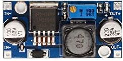
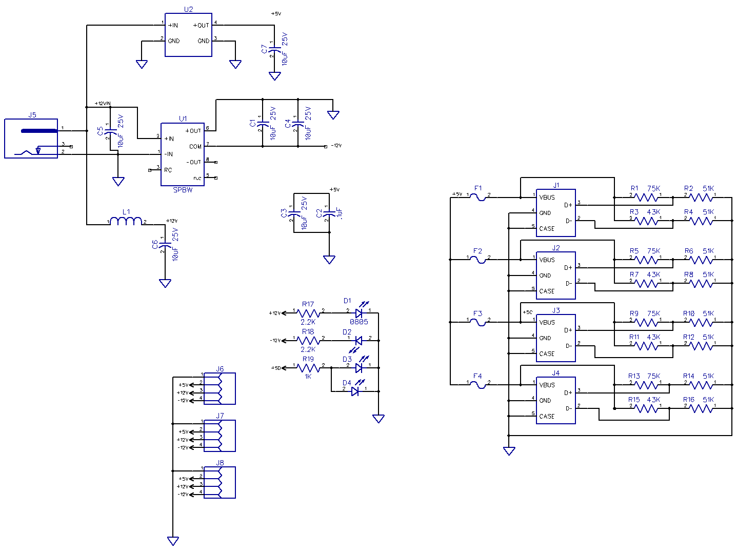
Yes I did use the cheapie Chinese buck regulator for U2. I adjust them for +5.1V output and added input and output ceramic (low ESR and ESL) capacitors. I use a 1A USB circuit for the 5V,and fuse each USB device with a self-resetting 2A fuse.

For -12V I use a  $7 12V to 12V DC-DC converter.

For +12V I just take the input +12V and distribute it to the four multi-voltage connectors.

For the +12V input I use a coaxial jack, 5.5x2.1mm, the most common one. Any +12V 3A to 5A power brick can power these. Or any 12V lighter plug cable. Make sure you use beefy 22AWG ore heavier cable. When I tried my 12V soldering iron with a 24AWG 6' cable on the boat,  it not work. Heavier cable worked.

For the USB chargers, I found that most things work fine with no current programing resistors. But then I found that Apple i-things didn't like this and would not charge. I added two 150K pull-ups to D+ and D-, and that seemed to satisfy my wife's iPod touch on a docking speaker.

Then I tried an iPad Mini. It worked but took for-e-ver to charge. These want 1A or more. For 1A, different resistors are needed: 2.0V on D- and 2.8V on D+. See the schematic below. Rev1 had no resistors, I just soldered them to the USB connector pins on the back of the boards . Rev2 has the four resistors  on each USB port.

J6-9 are 4 pin 3.81mm (0.15") pluggable screw terminals. These can easily be field wired, and then plugged or unplugged. When I need a standard 2.1mm or 2.5mm cable, I buy the cables (Digikey or Ebay) and build them up. Then label them for what they plug into. It is bad to plug a 12V cable into something that wants 5V.

When I run into a different size plug, I just cut the cord off the power supply and wire it into the correct pins.


sch

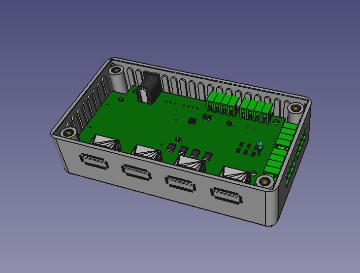
Here is 3D model of the board in a Hammond enclosure. Board 3D model was exported from Diptrace, then imported into FreeCad along with the Hammond enclosure mode. No buck regulator,  too much work to build up a 3D model. I often find decent 3D models on grabcad, but couldn't find one for these boards.

3d

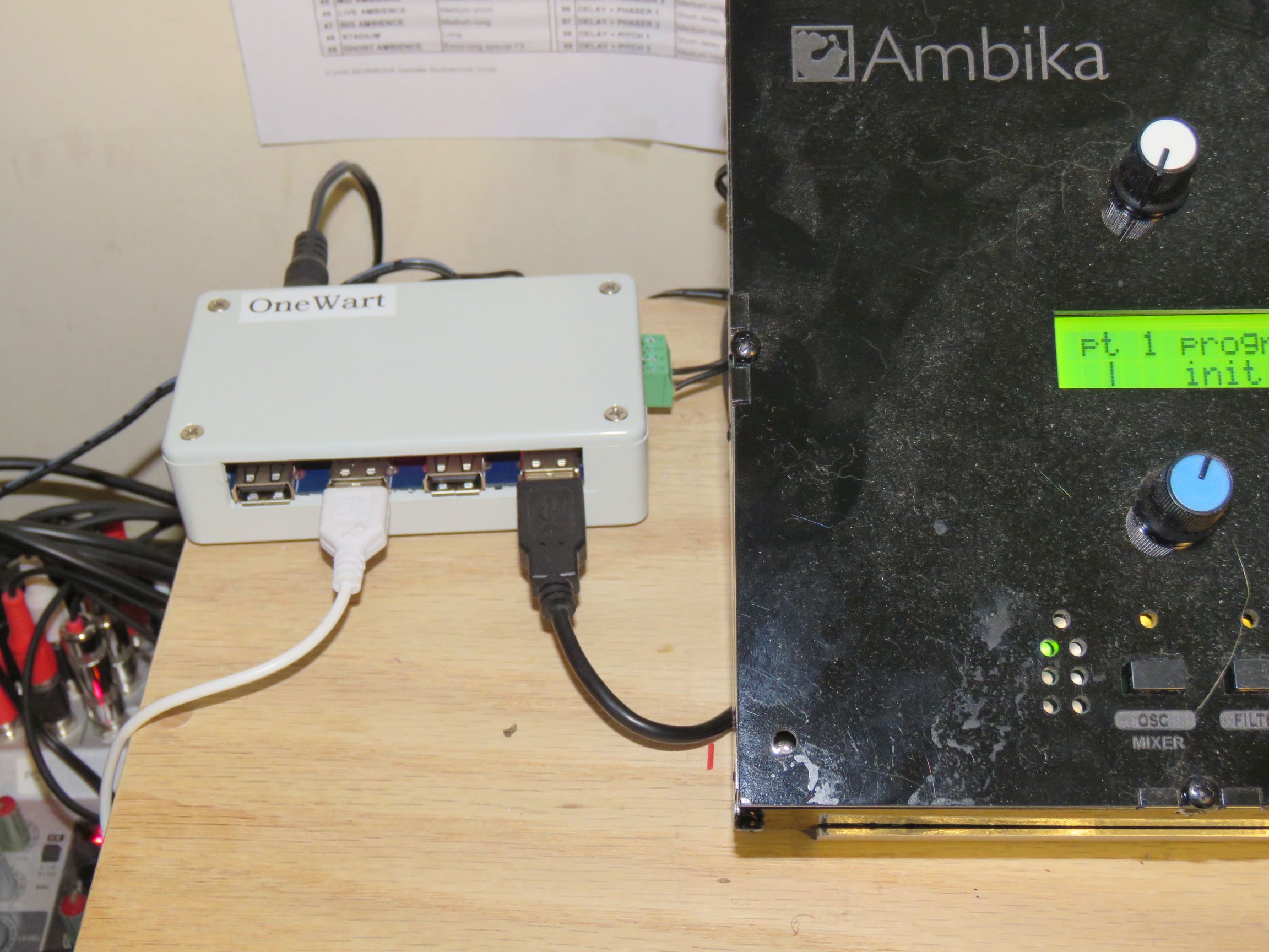
Here is a Rev1 OneWart mounted in a Hammond box with real parts. Cutting plastic slots for the connectors was more pain / work than expected. There are no good hand tools for cutting plastic. It is too thick to shear or cut with a knife, and too thin to saw or mill. I used a combination of a scoring knife for the horizontal cuts and band saw for the vertical cuts.
 
onewartbox

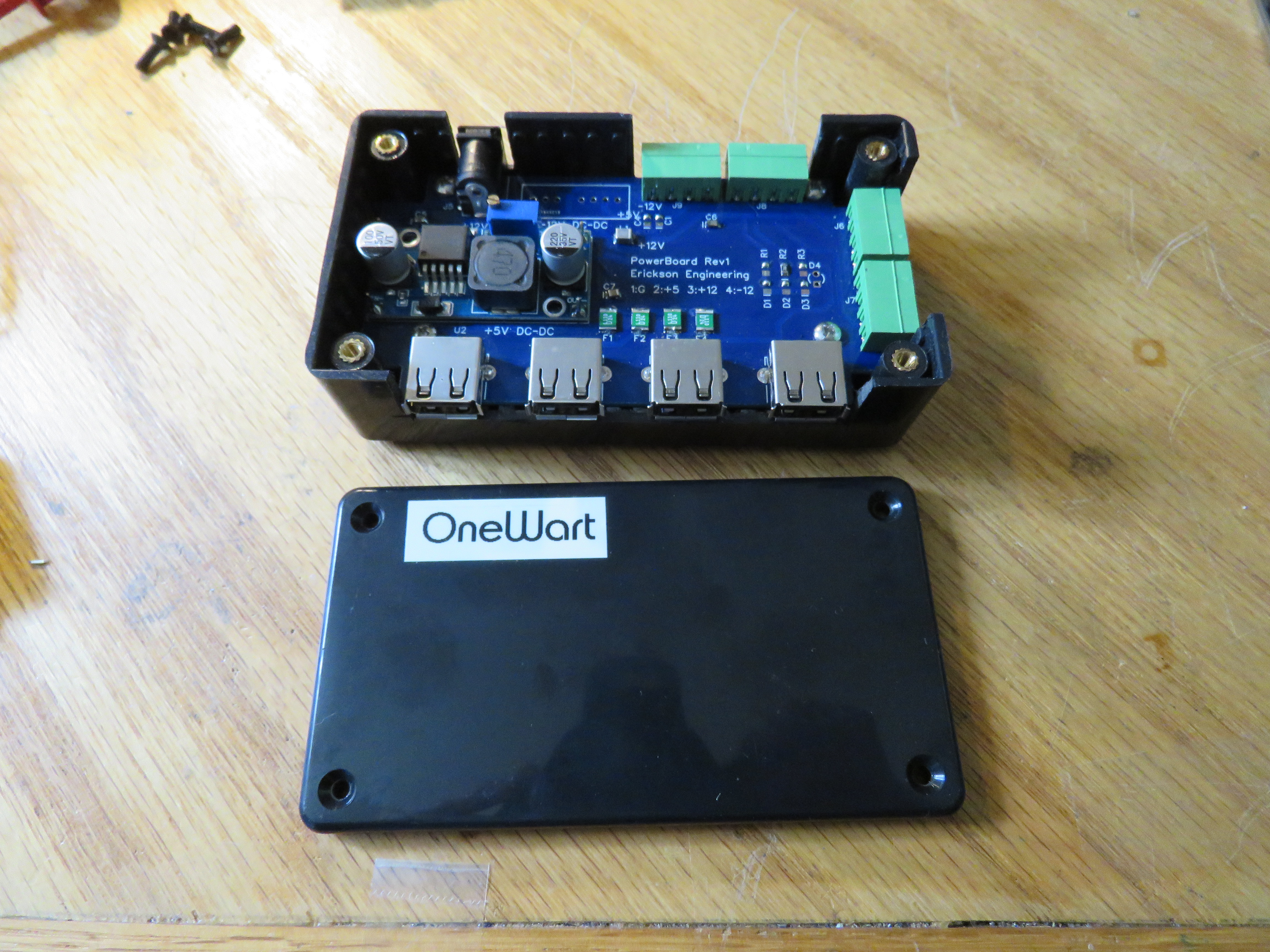
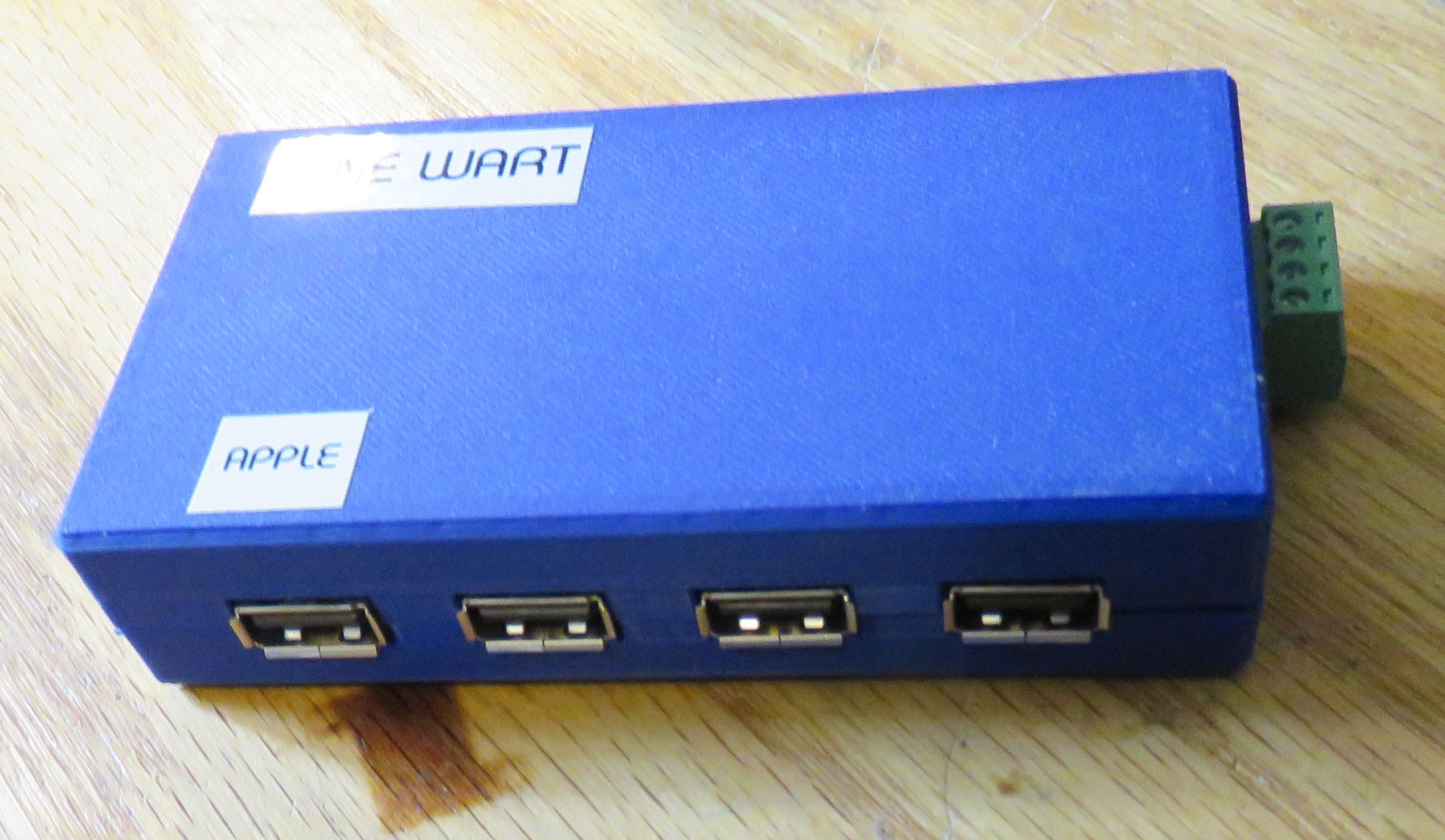
In a nice custom 3D printed box with one screw terminal connector plugged in. Thanks to Jimmy Su for designing and printing these.


3dprinted

Applications

I have three of these deployed in the house and one on the boat. A few more have been delivered to friends.

On the sailboat it works very well, running from a single car charger plug. We spent over a month this summer cruising Maine, and it came in very handy. It charged our 2 phones and the iPad mini, and ran our portable DVD player and 12V soldering iron.

At home I have one hidden behind the bedside table with the USB sockets pointing upwards.
bedside

For my music studio, this eliminated a handful of wall-warts. Some of the equipment says it wants +9V, but most 9V devices run fine from +12V.
music

On my nerd bench it powers various USB, 12V, +/- 12V and 5V projects. Very handy.

Future

Sure, it would be nice to have a current meter for each output. Maybe an Arduino with OLED display? Hmmm, OneWart Plus? Maybe one button to select the display. It would have to be pretty small to fit in the same case. For now I can plug in a USB power meter when I need to monitor a USB output.


  Dave's Home Page

Last Updated: 9/24/2021