Polysynth
Polyphonic Analog Synthesizer Project
The
Design files and Firmware for Polysynth are here
The Design files for Ambika 4P Filter
boards are
here
Link to Ambika Project
DIY Synthesizer -> Polysynths
I built a few DIY
synthesizer modules for Eurorack, based on others designs.
These are mostly modifications of other's classic designs which I
converted to SMT. Witthe wide availability of boards and front
panels, I built designs from kits or bare boards like
Synthrotek and Turing machine. I built a few microprocessor based
synth modules from O&C (Ornaments and Crime) and a couple of
Mutable Instruments clones. Then I learned about analog
polysynths. I love their full, rich sound when chords are played.
I read the excellent book on Dave
Smith and Sequential Circuits, particularly about the
Prophet 5. Prophet and Oberheim were based on analog chips
developed specifically for these products. Without custom analog
chips it would take too many components to build a reasonable
sized and cost analog poly-synth. Picture a big Moog modular synth
from the '70s. Now picture 5 or 6 of them to get a poly synth.
Yikes! Even 5 Mini-Moogs is a pretty scary concept. Yet this is
exactly what Dave Smith had in mind when he developed the Prophet
5 in the late '70s. His vision was to build a polyphonic Mini-Moog with presets. Without
those custom ICs for the VCOs (11), ADSRs (10) and filters (5) the
Prophet 5 would have been huge. As it was, an analog polysynth was
still an expensive instrument, selling for about $4,000 in 1980,
about $12,0000 in 2018 dollars.
Dave Smith used one of the few processors available at the time, a
lowly Z80 processor, and a single, and a single precision DAC
(digital to analog converter) to control all this synth goodness.
Good DACs were expensive hybrid devices, so he used a
de-multiplexing trick which was common in that day. The DAC used
low cost CMOS switches and opamps as sample-and-hold buffers. One
DAC could provide a few dozen of these de-multiplexed analog
outputs to control the analog synth elements. Dave was not only a
very good EE, but also an excellent assembly-language programmer.
Assembler is how most microprocessors were programmed in the day.
I have done a fair amount of Z80, 6502, and MC6800 programming. It
was fun and rewarding work. Since small C compilers for 8 bitters
became available in the '90s, I work mostly in C.
What happened to the early analog poly-synths? Sequential and
others built many, and were quite successful. Their sound was used
on many late 70s and early 80's songs and by many bands. As
processors got faster, they transitioned to hybrid analog /
digital machines such as the Prophet 600, and Roland Junos. But
when Yamaha came out with the all-digital DX7 FM synthesizer at
$1,500 in 1983, the analog poly-synths were no longer the only
game in town. Yamaha bought Alan Chowning's patents on FM
synthesis, which kept competitors at bay for several years. Analog
synth sales dropped and most companies could not develop and
manufacture these difficult analog machines for competitive
prices. Then by the end of the '80s, memory costs had dropped so
that sampling synths were now cost effective. These could
reproduce virtually any sound and that was the end of analog
synths. Without analog synths, the analog ICs used to build them
also went obsolete.
Fast forward to 2015 and analog synths have regained popularity.
Eurorack modular synths are very popular with hundreds and now
thousands of modules available. There are now three companies
building some of the analog ICs that were used in the'80s
polysynths. There is a resurgence of analog poly-synths. Some are
hybrid digital / analog and use DCOs (Digitally controlled
oscillators) since these are smaller, cheaper and do not require
calibration.
I looked into building an analog poly-synth. Many of the old
schematics and service manuals are available, particularly the
Prophet and Juno synths. It should have similar capabilities to
the Prophet 5 in terms of number of oscillators and modulation
capability. It should have a fully analog signal path, and digital
control to allow presets.
- 2 VCOs per voice
- Fully analog signal path
- Number of voices: configurable 1-8
(Prophet-5 has 5)
- Per voice:
- 2 VCOs
- Noise Source
- 7 input Mixer
- VCA
- Filter
- Flexible Modulation: FM, PWM, AM, Filter,
Sync
- VCOs are to have:
- Tri, Saw and Squ wave outputs
- Pulse width modulation
- FM modulation
- Hard sync one VCO to the other
- Coarse (semitone) and fine (cent) tuning
- Auto-tune: VCO frequency calibration
- VCF
- Separate module to allow installation of
various filters. T
- 7 input Mixer, able to mix any waveforms,
in any proportions.
- VCO1, 3 waves
- VCO2,
3 waves
- White noise
- Modulation sources:
- Envelope generators
and LFOs
- External
CVs
- V2 Triangle Wave
- Modulation destinations
- VCO FM (2)
- VCO Square wave PW (2)
- VCA
- Filter frequency
The Venerable Prophet-5:
Prophet-5 used analog envelopes and LFOs
generated by custom ICs. Its 4MHz Z80 processor could only update
the hardware slowly, fast enough to handle the keyboard and many
knobs, but not fast enough to generate ADSRs and LFOs in
real-time. 1KHz (1ms) is about the minimum update rate for these
functions. Modern processors can easily handle the speed and
computations to update a large number of channels at 1KHz or
faster.
DACs have gotten cheaper, but are not free. I plan to use 12 bit
DACs for the main oscillator tuning and 8 or 10 bit DACs for
the other functions. 8 bits is plenty for many functions, but more
precision may be needed for the Filter frequency to eliminate step
artifacts. My plan is to use 10 bit DACs for the other functions.
The low frequency operations such as LFO, MIDI, and ADSR will be
voltages generated by the 10b DACs. These will be generated in
Software and updated about 1KHz.
Prophet used analog control signals from their de-multiplexed DAC
to control many functions, and bused some of these signals to all
the voices. Since I plan to have digital control over many of
these, and since the DACs are cheaper, I plan to use an 8 channel
10b DAC for each voice.
Soon I was drawing schematics for the voice channel.
Mixer
I looked at many different mixer architectures,
and decided that the most flexible, smallest, and cheapest architecture was to use digital potentiometers.
Microchip makes a nice quad DigiPot part with 8 bits of resolution
for about $1.20. Two of these plus a summing op-amp make a nice 8
input mixer with SPI control. And unlike many synths where you can
only select one waveform, this approach allows one to mix multiple
waveforms from each VCO. If I decide later that a simpler waveform
selector is needed, it to can be built with a full mixer. Compare
the Digital pot to other arrangements or to DACs -> VCAs and
the cost and size is much higher. Using the Digital Pots
requires some tricks though.
After building the first boards, I discovered that the mixer was
not ideal. Since each audio signal from the '3320 VCO had DC on
it, the digital pots caused the DC level to vary as well as the
waveform level. This problem was harder than I thought.
- Each waveform (TRI, SQU and SAW) had a
different amplitudes and DC levels
- The EEPOTs can only handle 0 to +5V signal
levels
The solution I chose is to scale all the
signals to 0 to +4.0V with fixed resistors. Then their DC levels
are all +2V. The instead of having all the EEPOTs - sides go to
ground, have them go to +2V instead. This required a stable +2V
bias supply. See the schematics below.
Modulation
For the modulation, it is desirable to have many
inputs and outputs. Inputs can be:
- Envelope(s)
- LFO(s)
- External CV inputs
- VCOs for FM
Things that want to be modulated (outputs) are
- VCO Pulse Widths (2)
- VCO FM Inputs (2)
- VCA
- Filter Frequency
There are about 6 inputs and 6 outputs, and multiples of these are
needed at the same time. I looked at many approaches and decided
that an analog cross-point IC, about 8x8, would be nice. I chose
the MT8808 part that I have used on my whole-house stereo as a
signal selector. It costs about $8.
Digital Control Bus
To control the various DACs, Digital Pots and the
cross-points, a digital control method is needed. I looked at
parallel, SPI, and I2C. Parallel is too fast, I2C is too slow, and
SPI is just right. SPI can clock all these devices at about 10MHz
so updating a 10-12b DAC takes 16 bit times or under 2us. With 10
DACs per channel and 8 channels, that's 160uS, if every DAC is
updated every cycle. That's about 6KHz, and I figure 2-4KHz is
enough for the control channels. Plus, not every DAC is updated
every cycle, the cross-point and mixer pots can be updated only
when changes are made, and more slowly. I plan to add a global
addressing mode where all the channels can be selected and
controlled at the same time. Useful for Mixers and modulation
selection, but not for pitch and envelopes which need constant,
independent update.
So how to access about 4 SPI devices per board on up to 8 boards?
Some type of board and chip addressing is needed. The 3 main SPI
signals, SCK, MISO and MOSI pins can be common to all devices, but
the /SS (select) signals need to be separate and independent for
each device. The CPU can just output 3 board address pins and 3
chip address wires, and this will access up to 64 SPI devices.
But...
- Decoders are needed for board select and
chip select.
- A few board-wide control bits are needed.
- ~32 SPI loads on the common SPI signals is
excessive and will cause noise and signal slowdown. Buffering
on each board is needed.
- Some type of board select mechanism is
needed. Old-school address jumpers are a pain.
A handful of glue logic
is needed on each channel board. I recently used Xilinx Cool
Runner CPLDs for a small low-power design. These are cheap (<
$2), low power, small, low pin count (44) and easy to program in
Verilog (or VHDL). For the address selection, I decided to use
'geographic addressing'. With this method, the first board is
always address 0, the second is address 1, etc. One simple way
to implement this is to subtract 1 from the 3-bit board address
and pass it to the next board. Each board is selected only if it
receives address 0. If 3 bit address 0x0 is received by board 0,
it is selected, and sends 0x7 to the next board, which sends 0x6
to the next, and so on. So only board 0 is selected. If address
0x01 is sent, the first board is not selected, and sends 0x00 to
the second board, which is selected. This requires only a 3 bit
subtract on each board which uses little logic.
This type of addressing
requires separate Address IN and Address OUT pins for each
board. So it cannot be used with a simple backplane that is
common to all boards in a system.Or with simple 1:1
stacking connectors. It requires separate IN and OUT connectors,
at least for the address pins.
Stacking Connectors /
Mounting
I have used stacking
connectors with 0.8mm pitch on several previous designs. These are
low cost, high density, stacking connectors with various metric
board spacings. They used to be called "Amp Free-Height"
and are dense, low cost, and very reliable. They can be mounted on
opposite sides of the same board. I chose the 40 pin connectors
with 10mm inter-board spacing. This spacing allows the filter
module to be mounted to each channel board using smaller 20 pin
connectors with 5mm spacing and 5mm standoffs.
For the channel board mounting hardware, four 10mm M2.5 standoffs
are used. These are male-female types to allow additional boards
to be stacked.
For a front panel, I have not come up with a design yet. I
envision two sizes, one to accommodate 1-4 voice cards, one for
5-8 cards.
DACs
For the two pitch DACs, I chose the Microchip
dual 12 bit MCP4822. These are low cost ($2) and have reasonable
INL (accuracy). Their offset and gain and drift are quite good. My
plan it to initially have a trimpot for the V/Octave slope, and
each channel will be trimmed for 8 octaves of range. 4096 counts /
8 octaves is 512 counts per octave. I plan to use 500 counts per
octave, leaving 4096 - (500 * 8) - 96 counts for the software
offset adjustment. Since the DAC and he VCO are on the same board,
it is sensible to adjust the slope for each channel.
Here is a list of VCO error sources. VCO errors can be divided
into those that cause offset errors, those that cause slope
errors, and those that cause temperature drift of these 2 factors.
ADC non-linearity also causes errors.
My goal is to have the total errors be on the order of +/-0.1
semitones (10 cents) at middle C, and +/- 0.2 semitones across +/-
3 octaves from middle C. Errors on the extreme high and low
octaves can be a bit higher. VCO Error
sources in '3340 type VCOs:
- '3340 VCO IC accuracy: offset and
slope
- 1000pF 2% NPO Capacitor: offset and offset
drift, estimate 100ppm
- 1.8K 1% 100ppm resistor: slope and
slope drift
- Reference resistor: 1Meg 1% 100ppm offset
- Offset resistor: 301K 1%, 100ppm/C: offset
and drift
- +10V reference, +/-0.2%, 30ppm/C: offset
and drift
- R1/R2 5.6K 1% and 28K trimmed: offset
and slope, tempco
- MCP4822 DAC Reference drift: 10ppm/C
Supposedly the trim on R1, the 28K affects the
temperature drift of the VCO. I use it to set the oscillator to
1V/Octave. After setting this, I found that all that is needed is
a digital (software) offset calibration for each oscillator. The
first 6 oscillators I built were within a few semitones of ideal.
This is good since each semitone of calibration affects the DAC
range. I'm aiming for 8 octaves of range. but probably will need
to adjust this down a bit to allow for calibration of +/- 3
semitones or more. For now each oscillator and DAC has its own
maximum note which is weird: each one tops out at a different
note. I'll need to clip them all at the same note.
I have read all the articles on tuning '3340 oscillators. But
there are still unanswered questions when you want to minimize he
number of trimpots. I want to keep the tuning as simple as
possible and as few trimpots as possible. Supposedly the 28K
affects the tempco, but it affects the V/O tuning and the offset
as well. Supposedly to get ideal temperature tracking, the
currents into pins 1 and 2 should be the same. A trick to adjust
this is to place a second 5.6K resistor in series with 20.4K to
make the 28K, then adjust the 20.4K until you get 0mV across the
two 5.6K's, insuring that both pins have the same current. Clever.
I'll try to see if a fixed resistor can come close enough, then
tweak the 1.8K for 1V/O. Sequential Circuits Prophet 5 uses only
one trimpot per channel, the 28K. But Prophet 5 has a powerful
auto-tuning, a pitch linearity cal per octave, and also have
tuning stability issues. Maybe they didn't figure out the optimum
analog solution. Hmmmm.
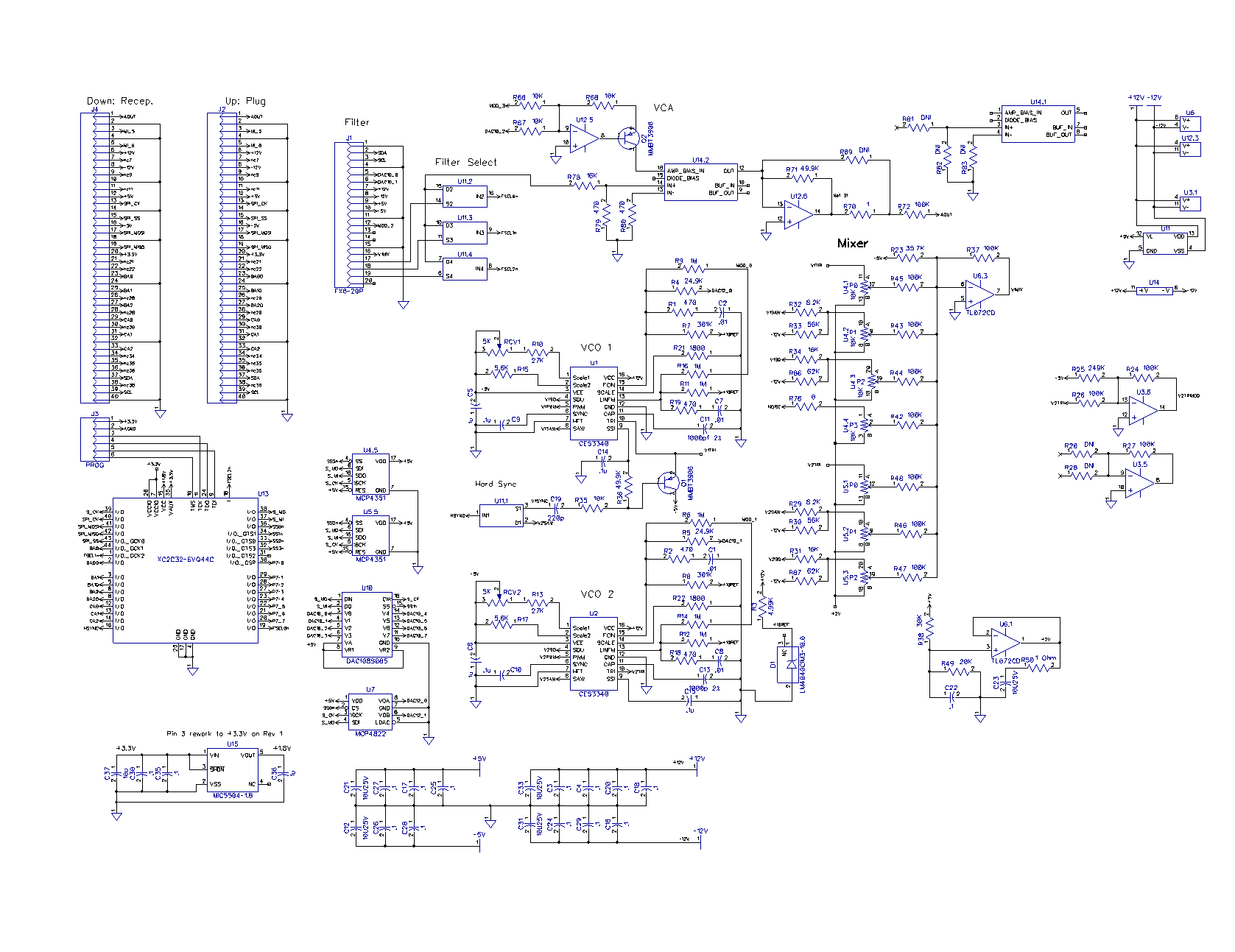
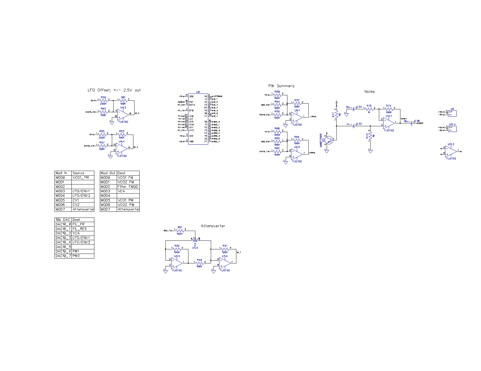
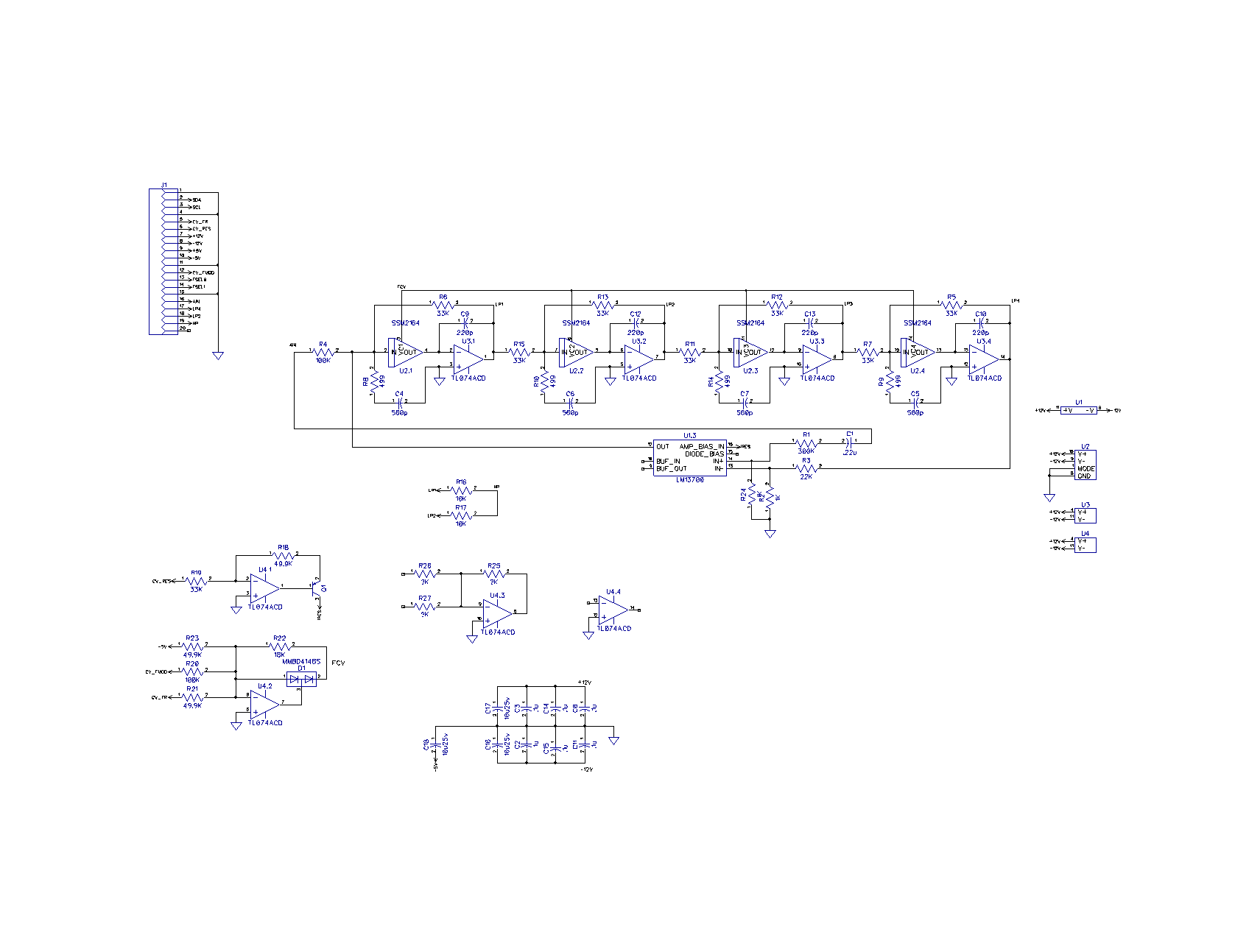
Here is the PolySynth channel board schematic.
Here is the Filter Board
schematic
Ambika Side Project:
Important Distraction
As I was working on Polysynth and dealing with the software
design. I began to realize that I had to design a lot of stuff
without ever seeing or using a proper Analog polysynth. About the
time I was getting overwhelmed by my lack of experience, I came
across Ambika. Ambika is a DIY polysynth from Mutable Instruments.
It was designed in about 2010 by Mutable Instruments brilliant
instrument designer Émilie Gillet, and is now
owned by Tubika who support it nicely. Ambika is a 1 to 6 voice
hybrid polysynth with individual channel boards and analog
filters. I dove in and discovered that Ambika and Polysynth
have many things in common. Ambika has:
- Voice per board,
variable # of voices.
- Different filter
options
- Nice MIDI interface
- One filter option is 4P: the same as
Mutable Ripples, the same as Polysynth
- SPI control of voices from a a master
processor
- Similar UI: multiple displays and knobs, a
simple and shallow menu structure
- Open HW and SW: C++ source code available
- Tons of modulation options
- Stores patches on an SD card. I want this
feature.
Ambika has some other nice features. A major
difference is that Ambika uses digital oscillators based on a $2
Mega328P processor, the IC used in Arduino Uno. These are cheaper
and more flexible than analog, and don't require tuning. The
Filter and VCA are very similar to what I use on Polysynth.
Identical in fact, since I stole the first Polysynth filter design
from Mutable Ripples. This is the same filter used by the Ambika
4P Voice cards.
Ambika got good reviews, folks liked it, and I like the sound. So
I decided to build one. I wasn't crazy about the cost ($50 for the
main bare board, $20 x6 for the voices, about $600 for a full kit)
and the pre-programmed processors aren't cheap. But programming an
Atmel Mega isn't rocket science. I decided to build a Budget
Ambika:
- Buy and build a main board. I found a
bare-board for $25
- Design and order my own 4P SMT channel
boards: $35 for 10 bare boards vs $120 for 6.
- Program the 7 processors
myself: $3 each vs of $20 each
- Order the parts from Digikey and Mouser,
and use ICs and discretes from my lab stock.
- Order a plastic case for $40
I'd guess I built my Ambika for about $300 BOM
cost, plus a few days of design and assembly labor.
As a test, I programmed an Arduino Mega328 board with the Ambika
Voice card .HEX files. After installing Atmel Studio, it was a
piece of cake, using my $30 AVR-ISP MkII. So I bought a
mother-board and the parts and started the build. The mother-board
parts were easy to find and fairly inexpensive. Since I already
stocked many of the parts for the voice cards in SMT, including
the DAC and V2164 filter chips (used on Polysynth), and I can
order 10 boards from China for about $35 including shipping, I
decided to redesign the 4P filter voice card in SMT. Plus I prefer
to hand-build SMT vs. thru-hole boards.
I was able to import the Ambika Eagle CAD files into DipTrace,
then update the footprints to SMT, and presto, the schematic and
PCB placement was done including board size, mounting hardware,
and connectors. Then just clean up the broken traces, and a few
hours later the board was designed. The only real "work" was
changing the DIP Mega328P processor to the 28 pin SMT version: the
pin numbers are all different. I changed a few parts to make them
easier and cheaper in SMT. The 220pF 2% filter caps were
originally film types. I used 0805 NPO ceramics which have nice
electrical characteristics and tempcos. The bulk bypass caps were
100uF electrolytic. I used 22uF ceramics in a 1206 package. It's
an easy 0.050" pitch build except the fine-pitch processor, and
even that is 0.8mm pitch, not so bad. I like that the stacking
connectors are the same as used on Arduino, available and cheap. I
checked the pinouts and the mechanical dimensions carefully, then
ordered boards from PCBWay in China. A week later the boards
arrived. Stuffed the mother board and one voice card, and
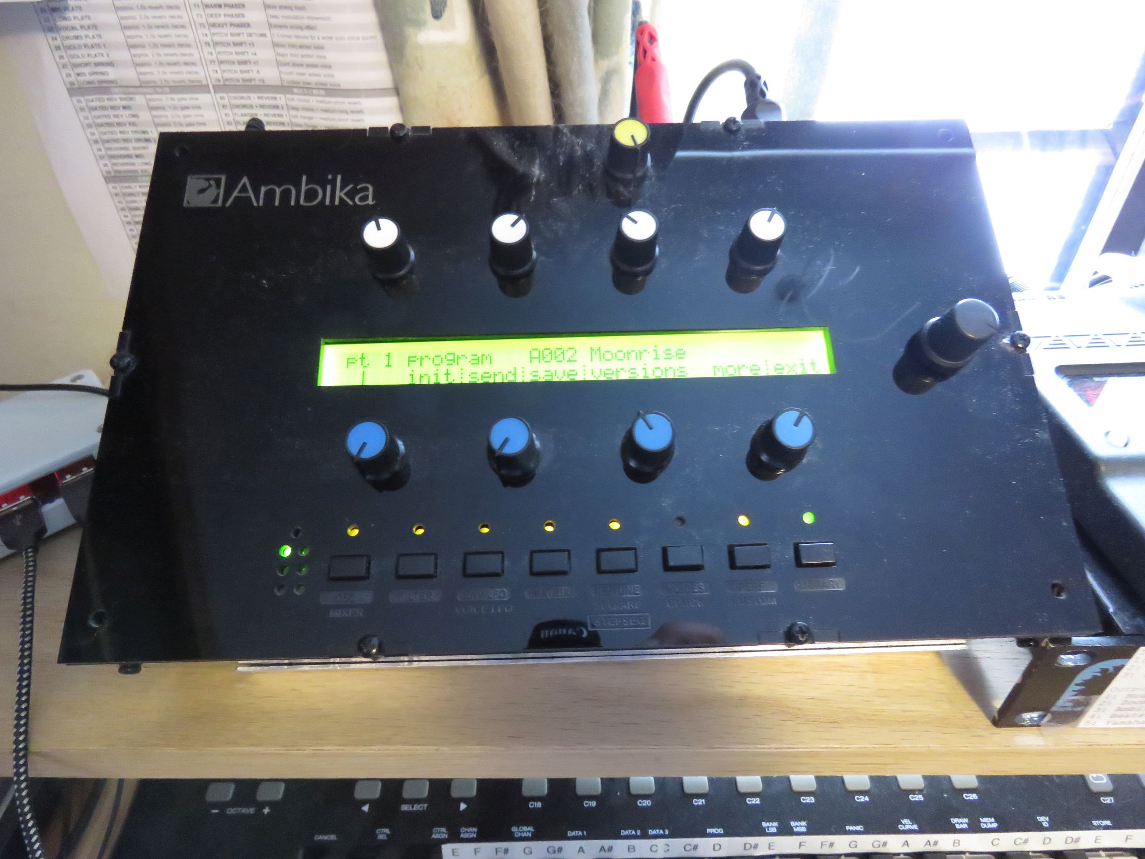
programmed both boards. The motherboard came up right away and
displayed the menu on the LCD. But I found that care must be taken
to get all the programming fuses right. The channel board took a
bit of checking, but it too came up. Checked the parts and
soldering on both, and it finally output a sound but only on every
third note of the keyboard. I Set the Ambika channels to 1, and it
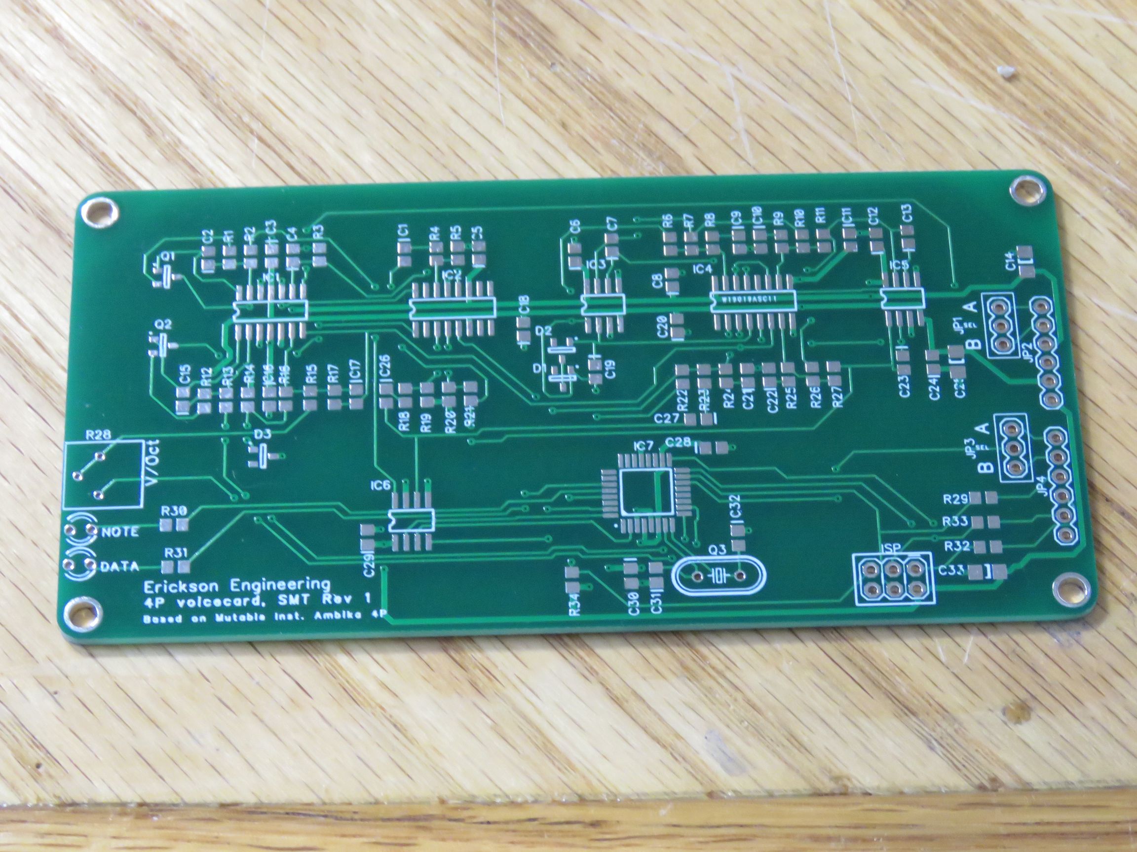
worked fine. Then I built 5 more voice cards. Here is my 4P voice
card bare-board.
I enjoyed building and then playing with Ambika. I learned a lot
about analog polysynths.
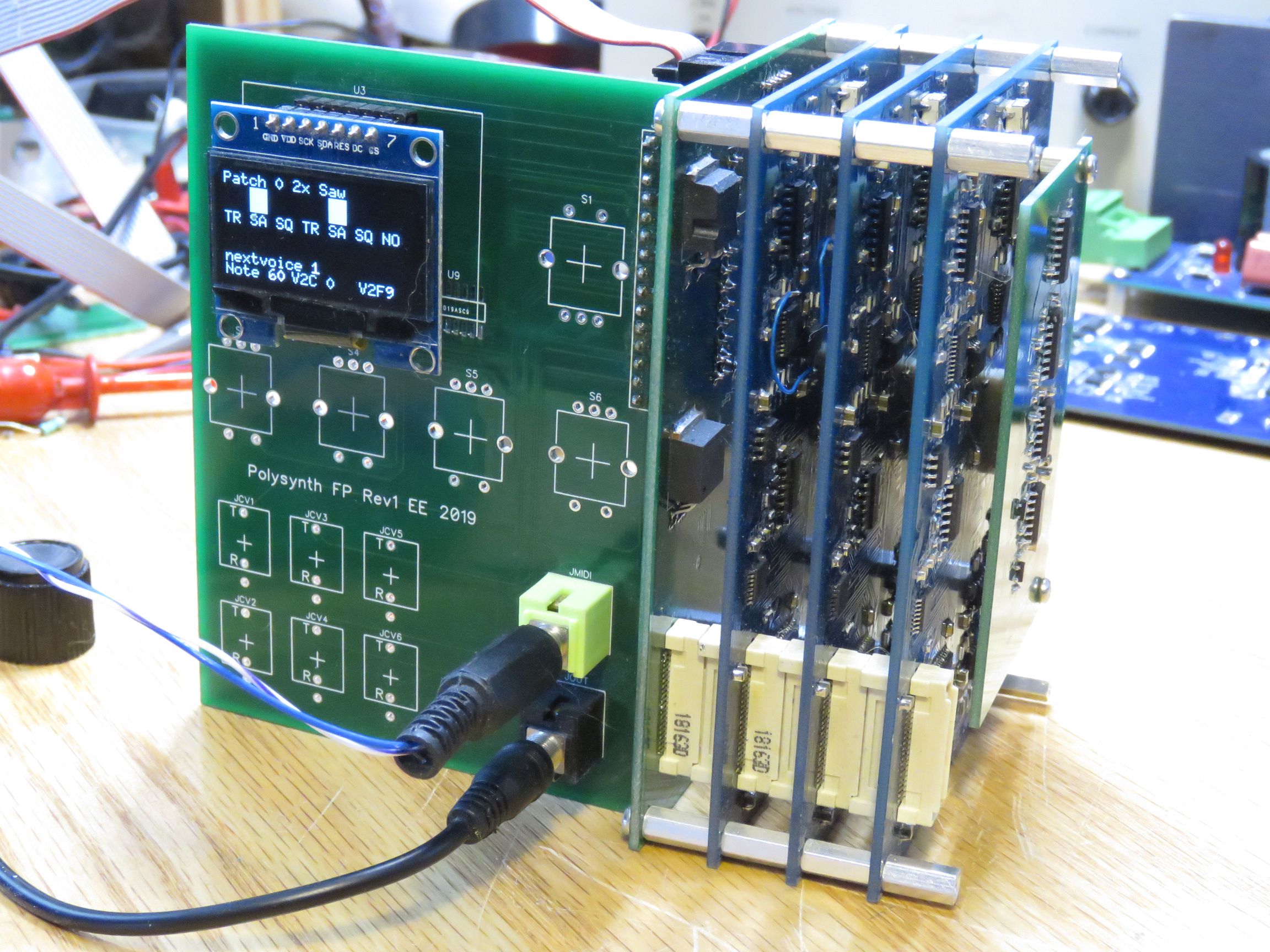
Back to Polysynth: What's left to do?
A single 4-voice Polysynth is built and is making music. I
currently use the default MIDI controls on my M-Audio Oxygen49
keyboard to set a handful of synth parameters.
- Filter frequency and resonance
- Select patch. Only about 10 test patches are
implemented.
- Mixer settings are hard-wired for each patch
I put Polysynth on the shelf for 2020 while I
pursued my DIY-SMU (Source-measure Unit) project. What's left on
Polysynth?
- Debug and write code for
Modulation Matrix.
- Filter tracking to
keyboard
- Improve calibration:
Auto-tune
- Needs Teensy frequency
counter code
- Rev 2 Channel
Board is designed. Reworks are fixed. Need to order and build
boards. Changes are:
- VCO waveform bias for Mixer
- Small reworks fixed
- Stacking connector footprints fixed
- Encoders and firmware
- Low-level encoder firmware
- UI for Mod Matrix
- UI for Envelopes (ADSR)
- UI for LFOs
- Better voice allocation algorithm
- Some type of front panel, probably
Eurorack.
Dave's Home Page
Last Updated:
2/18/2023