Raspberry Pi Power
Limitations: An EE's view
I recently built up a Raspberry Pi audio server. I want a better
way to access my audio files and do audio streaming without a PC
involved. Mostly I want to have access to my music collection,
mostly .MP3 and .FLAC (lossless) audio. I have built all my own
audio electronics since the early 70's. Everything from speakers, preamps,
power amps, disco mixers, boom-boxes, and several whole-house audio
systems. This is my first foray into DIY digital audio. I did the
homework to find available commercial and DIY solutions, and
considered a handful of home audio servers from DIY Raspberry-pi
to Multi-kilobuck audiophile systems. As usual, I am driven
by the concept of 'FREE'. I had an idle Raspbery Pi board and
decided to see what I could do with it.
I was looking for:
- Raspberry Pi audio
server
- Access to my 30 year
music collection, primarily .MP3: < 100GB so far
- .WAV and .FLAC files
- A nice Android /
Apple app to control it all
- Good quality audio:
16 bit, 44KHz and up
- Low noise,
distortion, and jitter: high every thing good, low everything
bad
- Streaming of Pandora
and Spotify, maybe others
- Line-level stereo
audio into my whole-house
stereo system
Volumio system on
Raspberry Pi
After watching a handful
of videos, I selected and installed Volumio v3 on my RPi 3B and
installed their app on my Android phone. I have only dabbled with
RPi's, am not an expert by any means.The install went very well,
and before long I was accessing my audio collection from a USB
thumb-drive and playing it out the RPi headphone jack: no DAC HAT
yet. Cool! The RPi was a typical octopus: Cables in all directions
from Power, HDMI, Ethernet, Keyboard, Mouse, and audio, plus a
thumb drive, pretty ugly. But after doing the install, I ran SSH
on PuTTY to provide a Linux console, and so could unplug the
keyboard, mouse and HDMI monitor. The magic was when I unplugged
the ethernet cable and everything continued to work via the
built-in WiFi. Got to love that Linux distribution.
Now the RPi only had only 2 cables: USB power, audio out, plus a
thumb-drive. Nice.
To get Pandora working on Volumio, I had to install a plug-in and
deal with the scary Linux command line. But the instructions on
the Github site truckershitch/volumio-plugins were pretty clear
and worked fine.
First Problem: Low
Voltage Warnings
The system worked well,
but I was getting fairly regular "Low voltage" warnings from the
RPi. I tried a few wall-warts, and different Micro-USB cables, but
no love. The RPi specifies a 5V 3A (actually 5.1V) power adapter.
I plugged in a Drok USB tester to monitor the voltage and current.
The voltage at the source was fine. > 5.0V. To my surprise, the
average current never went over 0.25A, even when driving the HDMI
monitor. I measured the voltage on the RPi's big diode D1, and it
was 4.75V. A better (thicker) Micro USB cable increased this to
4.8V. The low-voltage errors are probably when the power-hunglry
WiFi transmits RF. Sure, if you use your RPi's USB to charge a few
phones, the current will increase. Don't do that! I suspect that
the RPi power circuit is marginal with high loads.
Really, 3A over a Micro-USB cable and connector? That is a
ridiculous expectation The Micro USB pins are not specified for
that current, and the cable will have far too much IR drop. . The
RPI 4 uses the much improved USB C connector for power. I
investigated a few power filters and improvement. The good news is
that the RPi current draw in a sensible audio system is a low 250
mA or less. If you use a USB drive powered off USB, your power
will increase. Use a solid-state drive, USB thumb drive,
externally powered drive, or external NAS if you can.As of today,
1 and 2TB memory sticks are available for $30+.
Second Problem: Audio
Noise
Here's an irony for you.
When I disconnected all those extra RPi cables, the audio noise
went way up from barely-noticable to pretty-awful. It is caused by
a ground loop back to the grounded 5V power source.
Ground loops and their noise sources, 60Hz hum, and my old
nemesis, power supply
common-mode noise (CM noise) can be complicated. In this
case the problem was a ground loop. Particularly with unbalanced
(RCA) audio systems. In this case, I traced it to a
ground loop to my grounded +5V source, basically a USB hub. For
now, I wired a little 3.5mm
plug audio isolation transformer in the audio output.
Quieted the noise down nicely at the cost of a bit of distortion.
But my system was usable!
After a bit more experimentation, I found that an un-grounded (2
wire AC) wall-wart also worked well. But this will depend on the
quality of the power supply. If a cheap supply has a lot of CM
noise, it will also contribute audio noise. Listen to it with the
audio muted and the volume up. If it is quiet, you're good.
The quality of your RCA audio cables may also affect nosie. Cheap
audio cables typically have high shield resistance. Expensive
(generally stiffer) cables are lower. Due to Ohms Law, The Common
mode current Icm * Rc, the cable resistance induces a voltage,
Vcrud that adds to the audio signal. I began with using a
cheapie 6' stereo RCA cable. Turns out the HDMI cable to the
monitor was providing the RPi with a better ground-return path for
the common mode noise, and thus reduced noise! This is one valid
argument for high-quality (low shield resistance) RCA cables with
gold-plated connectors. Also the shorter the better, since shield
resistance is proportional to length. Lower cable shield
resistance improves the noise in a typical unbalanced audio
system, particularly when there are junky power sources in the
system. The right fix is to reduce the common-mode noise at the
power source.
Potential Fixes
The proper fix for CM
noise is to use a power supply with low CM noise. Grounded
wall-warts such as a USB Hub or other grounded AC power supply
will cause a ground loop. I experimented with a floating Lab
Power Suupply. As I expected, it was quiet. But when the power
supply - was grounded, the noise returned.
Since the power requirements are low, < 1A, a
linear power supply with a good low-common-mode transformer is a
decent choice. There are a handful of low noise / linear power
supplies intended for RPi audio systems.
Ian
Canada LinearPi Dual has filter caps and LDO regulators for
~$90. It takes in either 6VAC or 7-9V DC. But it does not address
CM noise source. You still need a low CM transformer or power
supply.
A second problem is noise on the 5V and 3.3V RPi power side
getting into the audio. I see various RPI power boards
designed to improve this power situtation. Some "audiophile"
projects go as far as to use SuperCapacitors and Lithium batteries
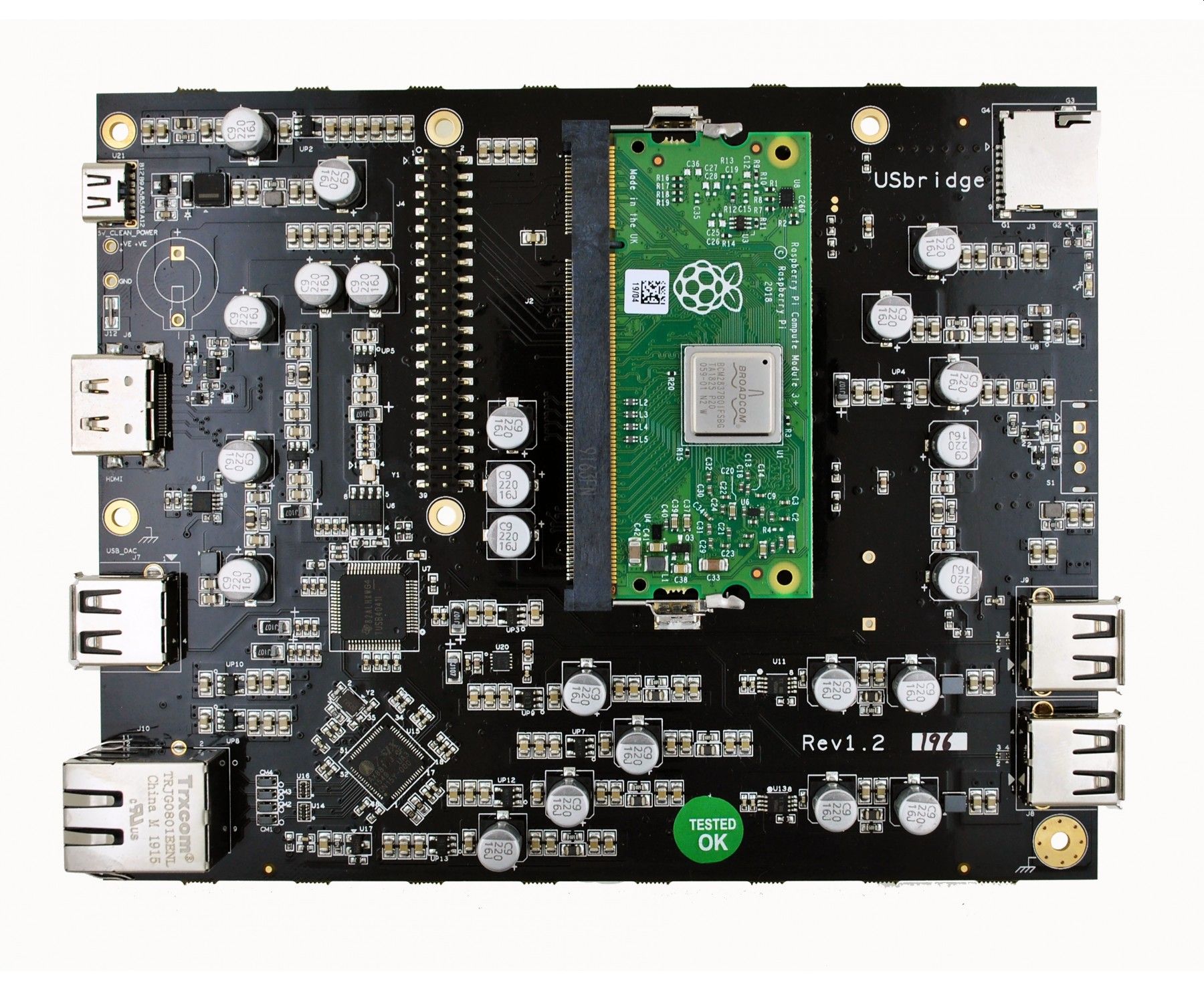
to power a RPi. Allo makes a
handful of power solutions in the $20-$300 range. Their UsBridge
at $240 is super-quiet using a RPi Zero module. It has dozens of
linear LDO regulator and filter caps for every IC and connector.
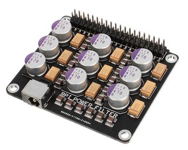
I see that Banggood and Ali Express offer RPi filter boards with
the name: "DAC Audio Decoder Digital Broadcasting Power Filter
Purification Module For Raspberry Pi3 3B 4B" for < $20. It
consists of a heap of (supposedly) high quality (AVX) Ceramic,
Tantalum, and Electrolytic capacitors. What could go wrong with a
Chinese board full of capacitors? I've been an electronics nerd my
whole life and this is the first time I've heard of a
"Purification" circuit. Love it. But seriusly, I like that
it replaces the iffy USB Micro power jack on the RPi 3 with a
nicer Coaxial power jack. With this board sandwiched between the
RPi and the DAC, it should help isolate the RPi noise and help
eliminate ground loops.
RPi 4 with USB C power would be a good choice too.
DAC HAT Boards
I ordered 2 different DAC
HAT boards from Amazon and an Ali Express Purification board.
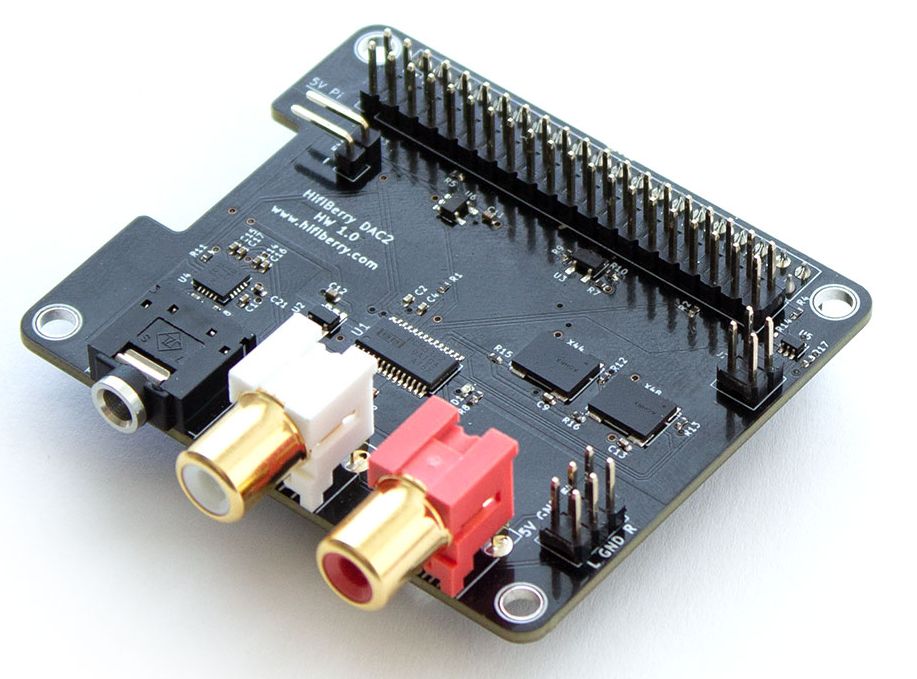
Couldn't resist. The DACs are HiFiBerry DAC2 Pro and HiFi DAC HAT
from www.inno-maker.com.
First one to come up and work, wins! Here is the HiFiBerry DAC2
Pro:
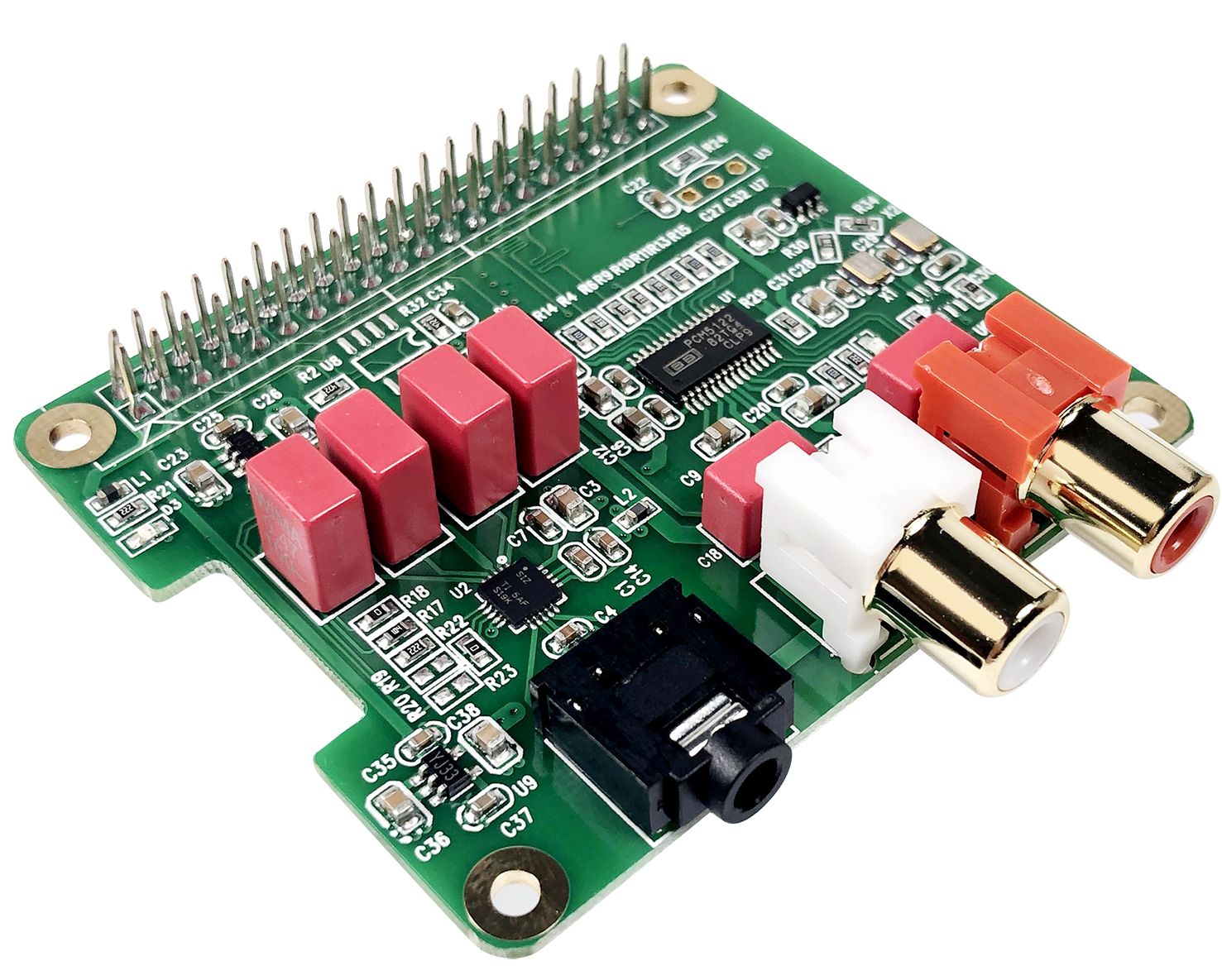
And the HiFi DAC Hat:
I received the DAC boards. The DAC2 Pro worked, but Volumio had no
specific DAC setting for it. After a brief internet search and
some trial-and-error, I found that the Volumio "HiFiBerry DAC2 HD"
setting works, but no hardware volume control. You'll need to use
software volume. But software volume just multiplies the 16b
digital data by a volume number of 0.0 to 1.0. This effectively
reduces the bit resolution of the digital data, and is worse at
low volume settings. Not great for a high-quality audio system. I
do like that it has header connectors for +5V and audio output.
These are handy for mounting your server in a larger enclosure
(below).
The HiFi DAC HAT works with the "Allo Boss" setting. Hardware
volume control work fine. For some reason it has an unreasonably
tall connector, requiring 16mm spacers. The standoffs that came
with the HiFi DAC HAT are pretty bad: too short for the tall
connectors, and cheap plastic. The official standoffs for RPi are
M2.5, but I found that #4-40 and #2-56 also work. #4-40 are a
tight fit in the RPi holes but can be coaxed in with a bit of
threading. They fit fine in the various HAT board holes. I used #4
7/16" for the Filter board and 5/8" for the DAC. I like
male-female (M-F) aluminum, 3/16 hex standoffs for board stacks.
Erickson Engineering doesn't currently stock M2.5 standoffs, just
#4 and #2. Those $10 brass M2.5 kits on Amazon look good.
Sound quality is very good with both DACs. I noticed that the HiFi
DAC Hat uses a 470 ohm resistor and 2200pFcap output filter. I was
using this board to drive an audio transformer directly and the
hum is pretty bad. This is not a good solution. Should have the
output buffered.
The "Purification" board arrived and I installed it. No problems,
and I can't tell if it improves noise. I'll need a proper isolated
5V power source with a coaxial power plug.
RPi Shortage 2022
I predicted this
shortage, kind-of. When RPi first arrived on the scene its price
was so low that I was concerned that the supply was susceptible to
speculation and hoarding. Now that has happened. RPi's are
completely out of stock from all the legitimate suppliers due to
semiconductor shortages, and only available from scalpers on Ebay
for 3-4x the list price. Fortunately for me, I have a friend who
claims to have so many RPi's in his collection that he uses them
for doorstops (JK!). When will this insanity end!!
Enclosure
I couldn't find a
suitable RPI case, and don't really want to have yet another box
in my living room, so will likely mount it inside the enclosure of
my whole-house
stereo. Inside there is power (+28V), enough empty space,
proper grounding, super-short audio cables, and adequate rear
panel space. The 3" inside height should be plenty of height for a
3 board RPi stack. Will experiment to make sure WiFi can get out.
Worst case I can use a plexi cover. I'll need to cobble together a
quiet +28V -> +5V DC-DC. The Purification board should help!
Better Audio Testing
I played a bit with REW
(Room Eq Wizard) free software which allows your sound card
to be used for audio testing. It is quite nice, operating up to
the maximum of your sound card. My old Creative Sound Blaster X-Fi
HD 24-bit 96KHz USB Interface Sound Card performed well up to
100dB SNR. The distortion is very good > 90dB at -10dBf, worse
at 0db. I like that it uses the sound card's capabilities. I ran
it at 24b and 96KHz sampling. I'd like to test the Volumio / DAC
combo as well as some of my home-built and purchased audio gear.
I'm thinking of installing an additional, newer, dedicated, and
better, USB sound card on my lab bench for this testing. That way
I don't need to take my PC sound system apart to do testing.
REW features:
- 24b Signal
generator: Sine, square, noise
- 24b Digitizer:
Scope, spectrum analyzer, waterfall plots
- Frequency response
- Speaker impedance
and response testing using a calibrated and amplified
microphone.
- 2 channels
I was able to quickly,
easily, and accurately, calibrate the input and output amplitudes
of my sound card using my Fluke 89 IV True RMS DMM. Any TRMS meter
will work. To do real audio testing, an ARTA-style interface is
needed. ARTA is a simple, manually operated switch box that does
input and output attenuation (and protection) and provides
standard impedance for speaker testing. I have in mind a smarter
ARTA with:
- Calibrated input
input and output gain and attenuation: -40 to +40dB, 6db
or 10dB steps
- Switch path for
loop-back
- Calibrated measure
circuit
- USB control
- 100+dB SNR
- Packaged to work
next to (or on top of) a USB Sound Card
- Maybe balanced I/O
- Some type of ground
loop eliminator: Big ferrite plus USB isolator?
- Advanced feature:
Notch filter for better distortion testing?
I suspect that the major
contributor to noise on most audio systems containing digital
sources will be the grounding and ground loops. Unfortunately a
USB sound card adds yet another noisy digital ground path to an
audio system. We'll see.
Clean Isolated Power
If you are building
hi-end audio equipment or precision instruments, I strongly
suggest that you watch Marco Reps
excellent video on AC leakage currents. He goes to great
measures to measure and then design low-leakage AC powered
equipment. How does this apply to Audio? With home equipment and
un-balanced connections everywhere, the line leakage current flows
through your un-balanced audio cable shields to find the shortest
path to ground. This is true for every piece of 2 wire line cord
audio equipment you have. They all induce leakage currents
into the audio grounds.
The commercial guys use well designed transformers with inner
shields between the primary and secondary windings. We mere
mortals, dealing with off-the-shelf transformers do not have such
luxuries. I know of no well shielded, off-the-shelf transformers.
But there are things we can do. Split-core transformers have
physically separated primary and secondary windings, and so are
quite low in leakage, typically less than 1uA, which is quite
good. 1uA of 60 Hz AC current through your decent RCA cable
grounds is pretty low noise: a typical cheap 6' RCA cable has
about 0.15 Ohms of ground resistance, so 1uA * .1ohms = 0.15uV of
60 Hz. Compared to -10dBV line-level signal (0.316V) this is 130dB
down. Multiple (stereo) cables in parallel, higher quality ones,
or shorter ones will all reduce the shield resistance. The problem
is that most audio equipment has much higher AC leakage, in the
10's of uA.
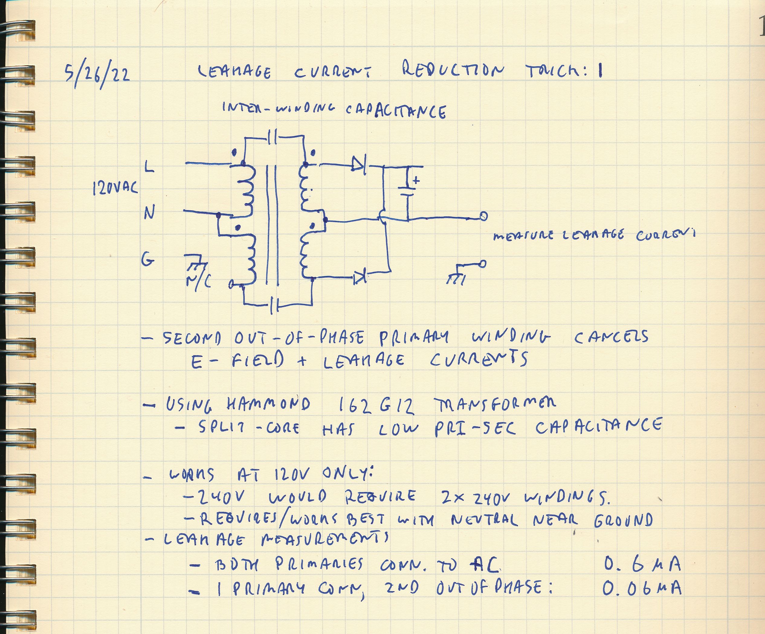
I just figured out a neat trick to reduce leakage on a split-core
transformer even lower than the typical 1uA, by about 10x. Tried
it on a Hammond 162G12, 12.6VCT, 12W. It reduces AC leakage
current by about 10x. The trick only works with 120VAC US power
and off-the-shelf dual-primary transformers. You connect one
primary of a dual primary AC transformer to the 120V line and
neutral. Then connect the other primary reversed, with only the
neutral connected, so it generates the opposite phase120VAC. The
other pin of the second winding is not connected, it just floats.
This out-of-phase winding cancels out the electric fields from the
primary, and so most of the leakage current also cancels. I get
almost a 10x reduction. Of course the transformer won't
perform as well with only one of its 2 primary windings connected:
Less total power, more V drop. But damn is the leakage current
low!
I'm trying to build a quiet, isolated, 5V linear power supply for
my Raspberry Pi music server. This trick will also work for
instrumentation. I plan to use the circuit below to drive a 5V
linear regulator. The transformer is 12.6VAC center tapped, 6.3VAC
per side. It generates about 6.3V * 1.414 - 0.7 = 8.2V DC.
Subtract a bit more for the ripple voltage, low line
voltage, and the single primary, and you should still get a
bit more than the 7.0VDC needed for a LM7805 type regulator's 2.0V
dropout voltage. LT1086 and others have lower dropout and higher
currents.
I may add a Common-mode filter to the AC line to reduce
high-frequency noise as well.
Clean Isolated Power
I'm aiming for a clean,
linear RPi power supply, simpler, low cost and DIY friendly.
Something anyone can build for themselves.
- Low common mode and
output noise and ripple. Lots of filtering
- +5V at 1.5A plus,
Enough for a light RPi system
- Very good isolation,
< 1uA AC leakage
- AC powered, IEC 3
wire line cord
- Maybe a line filter
for high frequency noise.
- Reasonably
efficient: Low-drop-out voltage
- Low cost: ~ $40
parts including enclosure
- As small and light
as possible
- Easy to build and
package: Off-the-shelf transformer, thermal design, and
enclosure, minimal machining, easy thru-hole and SMT soldering
- Safe and reliable,
fused, all line components UL/CE, but no overall safety certs.
Builder beware!
Good efficiency is
needed so this can be powered on 24/7 and not waste power. As I
pointed out, my current RPi music server draws < 300mA from
+5V, even when driving an HDMI display and keyboard. That's
about 250mA * 5V = 1.25W. I'll aim for 50% efficiency, so about
2.5W typical from the AC line.
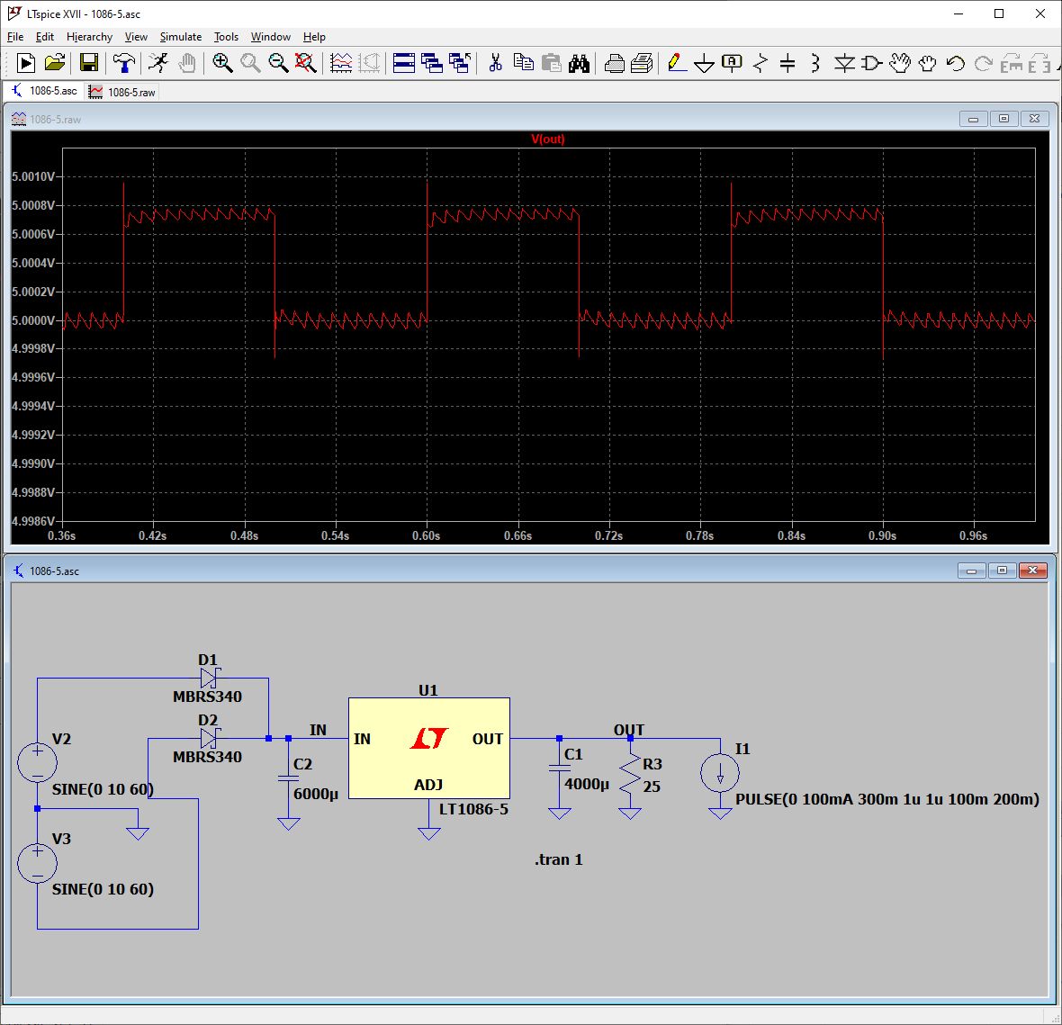
The LT/LM1086 regulator
looks good. Input capacitance and output capacitance is a
handful of 1000uF electrolytics in parallel. A 1000uF 20V cap is
about $.25. I plan to use 8-10 of them. Here is a simulation of
the regulator showing 120Hz ripple at about 100uV, and load
regulation < 1mV. Not bad.
Turns out I don't
really need this, but I thought it would be fun to build a RPi
server with high-quality power for DIY folks.
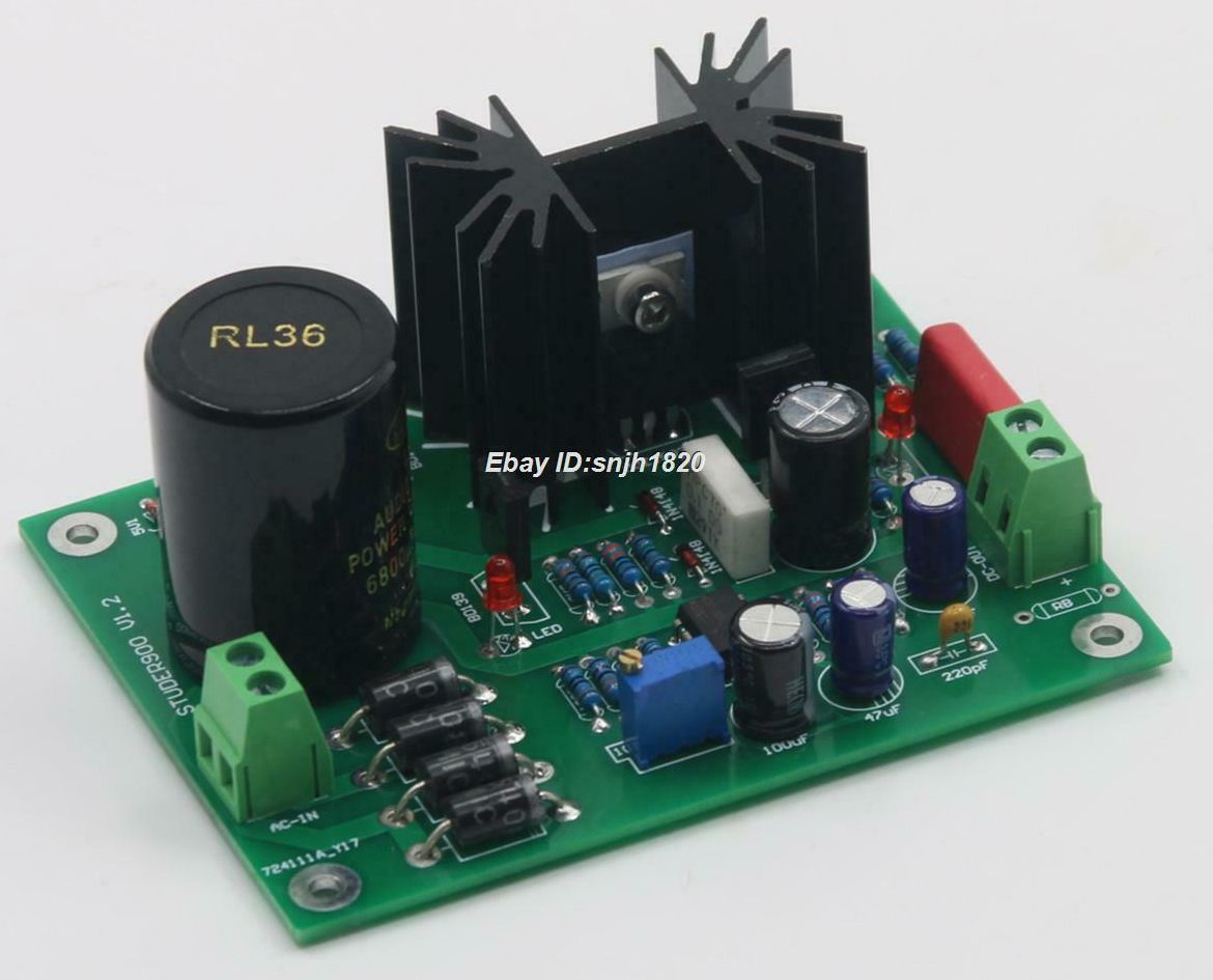
After a bit more
googling for low noise audio power supplies, I found several on
Ebay and Ali Express. I bought this Ebay one, couldn't resist
the $16 price for the board and components. The title is "HiFi
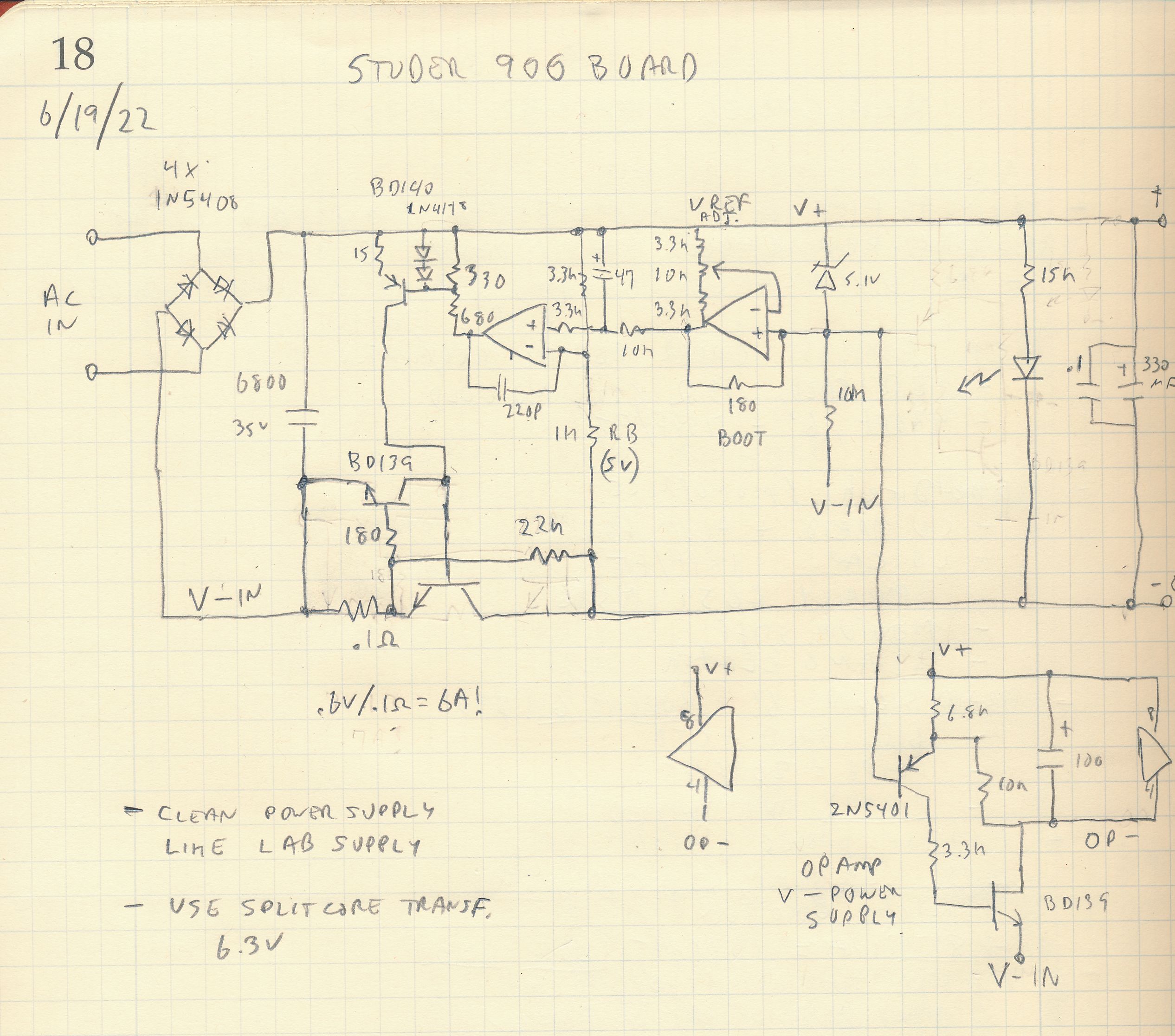
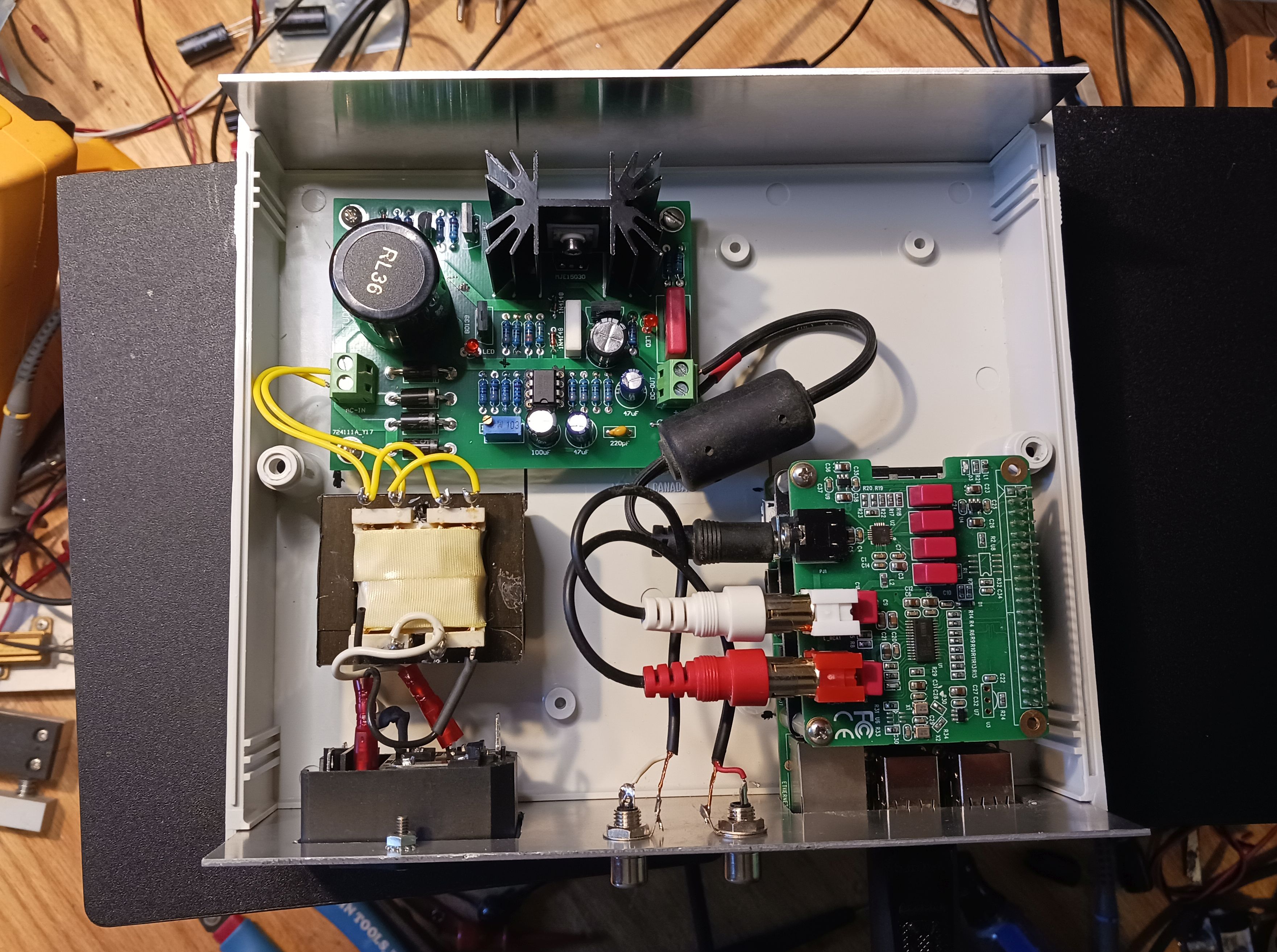
DC5V-24V Ultra Low Noise Studer900 Linear Power Supply Regulated
Board/Kit". It is based on a power supply design used in the
Studer 900 Swiss-made Studio mixing console. It is a decent,
discrete regulator design, similar to what you'd find in an old
electronics instrument.I built the board up pretty quickly.
Assembly went well.
I found a similar
Studer 900 schematic on-line and then reverse-engineered the
board to generate a schematic. It is a low drop-out design using
an NPN pass transistor MJE15030 in the negative path. So an
isolated input supply such as a transformer is needed. The
coarse output voltage is set by RB. Several values are provided
with the kit from 5V to 24V. I use 1K for 5V. The current limit
is high, about 0.6V / 0.1 ohms so about 6A Increasing the 0.10
ohm resistor would reduce the current limit. I'm thinking 0.33
to 0.47 ohms. It uses a separate negative power supply to
provide V- for the TL074 dual op-amp.
The output ripple and
noise are quite good, I measure under 50uV when driving a 0.5A
load, with a 6.3VAC transformer, wired with a single primary and
the "low leakage trick". I'll need to find a suitable enclosure
to house this board, an AC input fuse and filter, and
transformer.
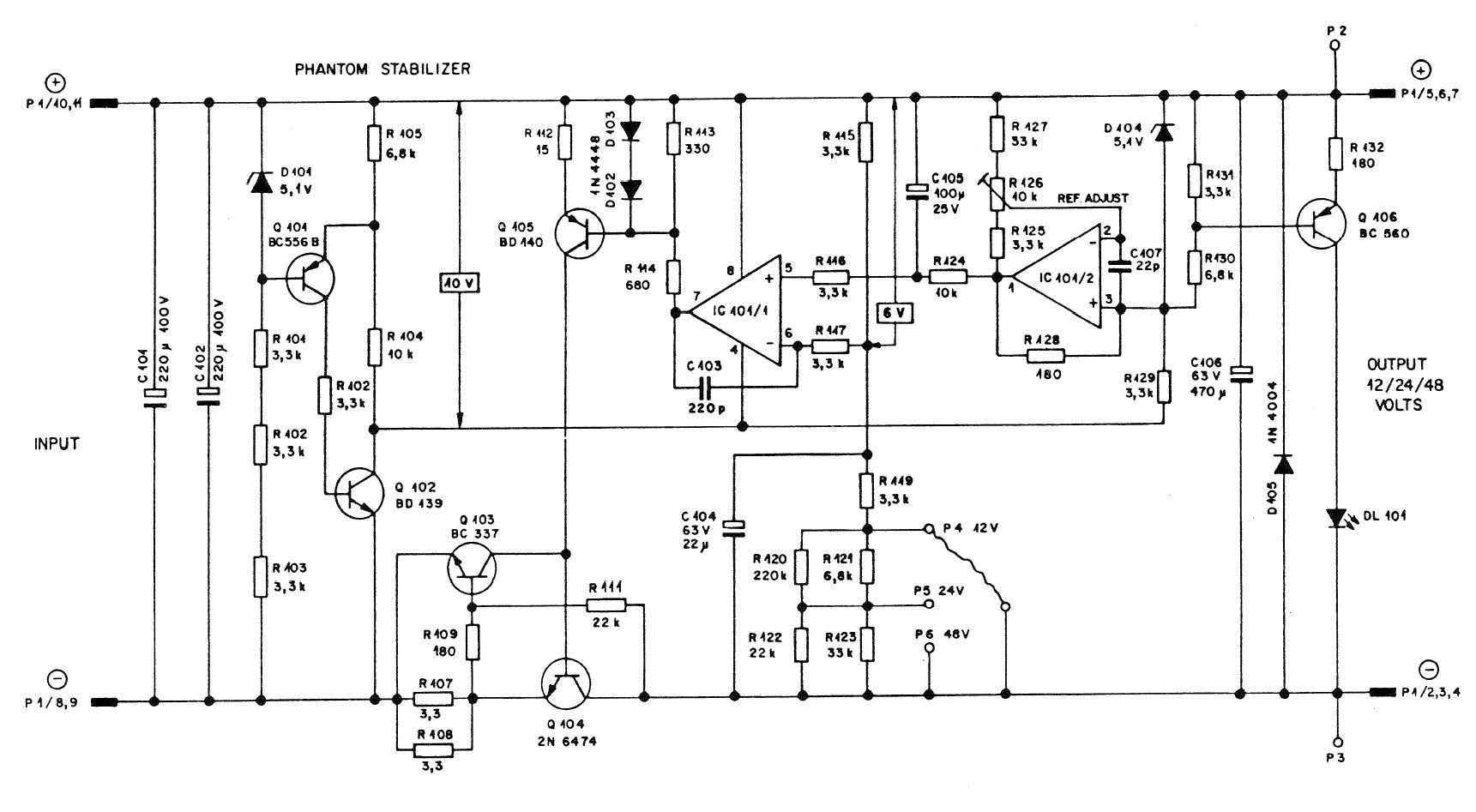
Here is the original
Studer900 schematic on which this board is based:
And here is the
reverse-engineered one I made from the board.
I measured the +5V
supply on my RPi audio server and found the largest contributor
to +5V noise. Is it the +5V regulator? The 5.5mF filter board?
Nope: it's the USB or 5.5mm coaxial power cable. This cable's +
and GND resistance (R) in conjunction with the RPi's widely
varying current drive cause the +5V to vary considerably,
particularly in the audio frequency range. My Studer900 supply
with a 24AWG 2m coaxial cable caused as much as 100mV p-p noise.
I swapped the high resistance cable with a 20cm, 20AWG cable and
the noise reduced considerably.
Clean, Switching,
Non-Isolated Power
I want to mount the RPi
server in my Whole-house
Audio system, in the existing case. It needs to squeeze in
along with the current 4 preamp boards and 8 channels of
amplifiers. The system has +/- 30V power supplies for the
amplifiers, and a +/-12V dc-dc converter for the preamp. There
is a small 5V regulator, but not enough power for the RPi
server. I'll need to convert the +30V to +5V at about 1A,
cleanly and efficiently. I plan to use a 30V -> 6V
non-isolated dc-dc switcher followed by a 5V LDO linear
regulator. I only need to build 1 or 2 of these, so planned to
build on a small proto-board.
For the 30V->6V
switcher, I first tried using one of the cheap, Chinese "LM3596"
blue, buck converter boards, but the output and input noise of
these is pretty bad, about 200mV at 55KHz. I want to begin with
a clean dc-dc. There are many choices, but the most convenient
are 3-terminal 780x replacements, and some small boards. I like
Pololu for small boards and have used their CPUs and motor
drivers in the past. Their small D24V10Fx switchers use the
ISL85410 synchronous buck DC-DC. I like that the output filter
uses multiple (6) ceramic capacitors to lower ESL and ESR.
However they do not specify output noise, so it's a bit of a
crap-shoot. I bought the 6V one for $10. 6.0V should
work fine. If I need to add extra L-C filtering between the
dc-dc and the LDO, I might need to increase the 6V a tad. The
output is adjustable over a small range but requires changing
one of the SMT voltage set resistors. For the 5V LDO I plan to
use a LT1085 or equivalent on a small heat sink.
The Pololu board
arrived. It measures 40mV p-p output noise at 500KHz with a 0.6A
load. Using no filter, and a LM1117 LDO board, I get about 20mV
of noise on the 5V. I'll need to mess with some LC filters to
reduce it further. This is harder than I thought.
I'm having second
thoughts about putting the RPI inside my Whole-house enclosure.
The Whole-house system is already complicated enough. And
removing / installing it to work on is not a simple process.
Besides, I use it every day. Putting RPi outside, in a separate
enclosure with its power supply makes life easier. I already
have a nice clean AC power supply for it.
Final Solution
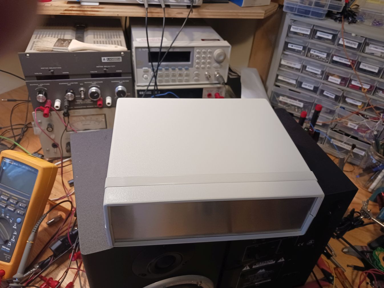
Here is the system in a
Hammond clam-shell enclosure, type 1598D which is about
8"x7"x2.5". The RPi USB and ethernet connectors exit from the rear
panel. So I'll need to reach around back to turn it on/off or to
access the USB thumb drive. I did this partly because we have
curious 1 and 3-year-olds at our house a few days a week.
The case is simple, and works perfectly but maybe not the most
beautiful. Any nicer case ideas?
I use a switched and fused AC inlet from Amazon. I had to decide
how to ground the rear panel. In order to avoid ground loops and
to minimize the AC leakage current, I'm purposely not using the
ground pin of the 3-wire AC line cord. If the transformer had a
mounting strap, I'd ground it to the AC ground to reduce leakage.
Also I made the opening for the RPI connectors large enough so
they would make contact with the rear panel. Instead, I just used
non-isolated (grounded) RCA connectors. They are the only thing
connected to the rear panel and since they are what provide the
external ground, it makes sense.
I decided to add a headphone jack to the box. I recently bought a
nice pair of headphones, and want to be able to listen to my RPI
server with minimal hardware between DAC and Ears. Unlike most DAC
HATs, The HiFi DAC HAT has a decent headphone amplifier built in.
All I need is a cable to connect the 3.5mm jack to a 1/4"
headphone jack on the front panel. I'll also add a power ON LED.
Dave's Home Page
Last Updated: 9/15/2022