Solar
System
Playing
with solar in the year 2023
Solar,
not practical here
Where I live,
the back of my small ranch house points directly south, but there
are many trees that keep my back yard and roof in the shade for
most of the day. Ironically we get more sun in the winter when
there are no leaves. And decent sun in the morning on the eastern
facing side. But that's not gonna keep me from playing. In 2021 my
friend Larry had a boat, and the three 120W solar panels on it
failed. He bought new ones and I got the old bad ones. Two of the
3 connection boxes had partially melted. The panels seemed to be
in decent shape. The diodes had fried in two of the panels. I
measured the raw panels and they indeed put out >
100W. Removing and replacing the diode boxes was pretty
simple.
These 3 panels are nominally 12V (closer to 18V). They have 4 x 9
= 36 cells each, which is typical for 12V panels. On his boat they
were wired in series to a charge controller which charged the 12V
batteries.
Why
did they fail? The diodes clearly overheated, but why? There
is a large Radar unit near the panels which partially shades the
panels depending on the boat angle to the sun. We suspected a
shading problem. Each panel puts out about 18V at 7A, But when one
panel is shaded, it's output drops significantly, and the 7A that
the other panels put out need to go somewhere. It goes into the
diodes of the shaded panel. The diode boxes typically have three
diodes in series. This puzzled me. Since they are getting constant
current from the other panels in series, what's the sense of using
3 diodes? That is 3x the voltage drop (wasted voltage) and 3x the
power dissipation of a single diode. Is it for voltage rating?
Bypass
Diodes
Since I was
puzzled, I built a LTSpice simulation of a solar panels to see
what was happening. A simple model for one solar cell is a current
source in parallel with a single forward-biased diode. Here is 2
panels in series, each with 36 cells. Each panel has 3 bypass
diodes in series.
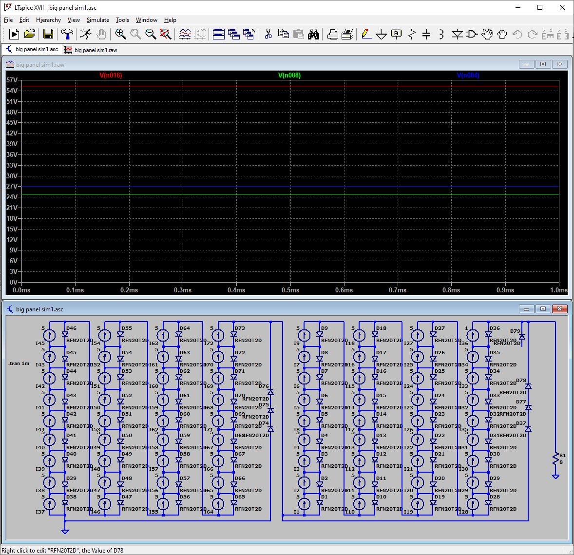
Each cell is outputting 5A, except for the upper right one which
is simulating a shaded panel that is outputing 1A. The first panel
outputs 27V (blue), and the 5A cells of the second panel raise
that to 55V (red), but the single 1A cell is back biased with the
full 26V of that panel, effectively reducing the output of that
entire panel to 0 A! The 3 bypass diodes conduct, and the
total output is reduced by 3 diode drops to 25V (green).
By
connecting a bypass diode D79 across the 1A cell, that cell's
back-bias voltage is reduced to only one diode drop, and nearly
the full panel output is output. Bypass diodes significantly
reduce the effects of partial shading.
In
the early days of solar panels, this shading effect was
identified, and many panels brought out the 1/3 and 2/3 connection
taps. This explains why junction boxes have 3 diodes in series. If
the intermediate taps were connected, a partially shaded panel
would only lose 1/3 of it's output, not 100% But many modern,
low-cost panels do not bring out the 1/3 and 2/3 taps. I assume to
save money.
Ideally each cell would have its own bypass diode. Some companies
such as Optivolt have technology
that helps shaded cells. I assume that's what they do.
But, using 3 diodes on a panel without any taps is bad. The 3
diodes dissipate 3x the power of a single diode, and also drop 3x
0.7V or 2.1V so the string is outputting 1.4V less than with a
single diode. All bad! The box is dissipating 3x the power
that it should. At 10A, this means 3 x 0.7V X 10A = 21W vs. 0.7V x
10A = 7W. And the box is mounted to the back of a hot solar panel,
so add another 40C temperature rise, and you have a recipe for
diode failure. This is likely what caused the diodes on Larry's
boat to fry. Another mitigating factor is that the mounting didn't
allow any air flow behind the panels.
Bypassing 2 of the 3 diodes would improve efficiency and
reliability. It won't help get more power out of a shaded panel
though.
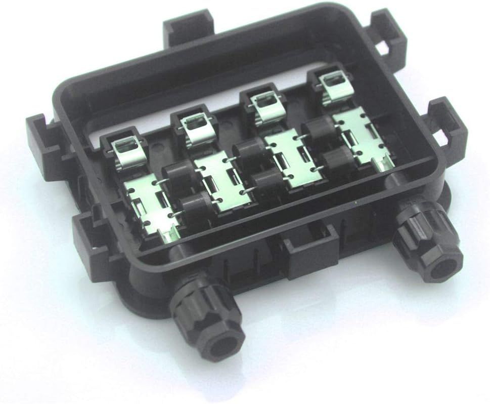
BTW
I notice that 3 diode junction boxes are hard to find. The current
ones on Amazon parallel 2 diodes and have 6 diodes as
shown above. I'll bet this is because of failures. Plus the fact
that modern panels output higher currents.
Y&H
WVC600 MicroInverter Teardown and Testing
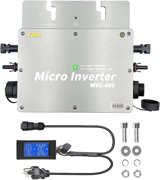
I bought
a low-cost grid-tie inverter from Amazon. WVB-600, 120V option.
The design looks good. It is designed to accommodate two 24V,
300W panels and has two set of MC4 connectors. These are tied
together in parallel inside the converter. Each panel has it's
own 15A fuse, so be careful if you tie the panels together
externally,
As far as regulatory approvals, it comes with a small CE
sticker. It has very few actual specifications. Not even
efficiency. It is designed for 28 to 50V, and has two solar
panel connectors. It is designed to accommodate two nominally
24V, 300W panels. Each panel connection is separate and
isolated. There is a single MPPT controller for the two panels.
Included
is a simple low-cost AC panel meter that shows how much power is
being generated. Cost is $140.
Clearly
the AC panel meter s not IP67 rated. To achieve the IP rating,
the panel meter would need to be replaced with a straight AC
power cord.
The enclosure has pretty good gasketing, and the connectors are
gasketed. It is intended to be used outside. It has an IP67
rating. Ideally it should be mounted in a cool, dry location.
Its thermal design is OK. Also mounting an inverter
outside behind hot solar panels and on a hot windless day
exposes it to another 20-30C or so temp rise. It is 'rated' for
600W, but gets quite warm when I use it with my 240W panels. I
measured efficiency at 240W and it is about 88-90%. If the
efficiency is the same at 400-600 600W, then the box will
dissipate about 60W when running two 300W panels. This is a lot
of power without forced-air cooling.
There
are reports of these shutting down due to over-temperature at
high power. I recommend that above 300W or so it should be used
indoors and have some forced-air cooling. A small 80mm,
12V, 2W fan should do pretty well. Gluing some finned heat
sinks to the cover wouldn't hurt.
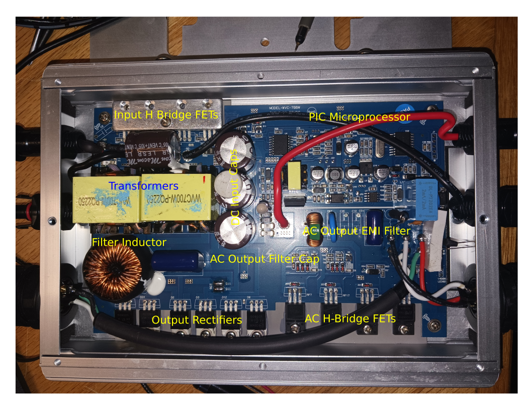
I
thought I would do some testing, a tear-down and some design
analysis. See if anything can be done to reduce temperature rise
and maybe improve safety and reliability. Maybe improve
efficiency?
I
powered it from a 24V lab supply. It drew about 5A current draw
did not increase beyond 5A. It really wants 28V minimum.
From a
28V, 250W, 9A switching supply, it draws the full 10A, causing
the supply to current limit at about 10A. It outputs 250W. It
shuts down and cycles ON/OFF due to the power supply going into
current limit when the output hits 250W. The measured efficiency
at 28V is about 250W out / (10A X 28V in ) or about 90%. Not
bad.
Here is
a decent description
of a grid-tie inverter. It is a
decent representation of the WVC-600. Except the WVC-600 doesn't
have the input boost converter. DC goes directly to the
H-Bridge.
Solar
Panel Simulator
To
properly test this inverter, I need a solar panel simulator.
Something that will power the inverter without the variations of
an actual solar panel. But real solar panel simulators are quite
expensive. Can I build a low cost one that works?
A
power supply is one solution. But power supplies have a sharp
current limit. And switching supplies aren't intended to operate
continuously in current-limit.
A
solar panel acts as a voltage source with a source resistance, and
then transitions to a current source as the load is increased.
Maximum Power Point controllers depend on this soft 'knee'. They
work by gradually increasing current draw to find the maximum
power. When the power begins to drop due to too much current draw,
they back off the current. Then they continuously increase and
decrease the current to find and stay at the maximum power point.
If there is no current limit, they may continuously increase until
they reach their current limit. If the current limit is too
abrupt, they may not be stable.
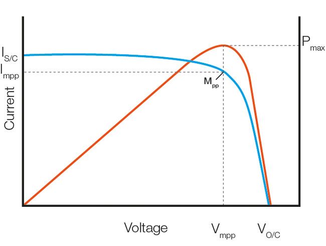
Here is a typical I vs V curve and Power vs V of a solar panel.
Power supplies are typically specified with Voltage on the Y axis.
The curve is pretty similar if you swap the axes. I will use
I on the X axis and V on the Y axis.
A
switching power supply will provide the raw power, but some type
of external current limit is needed. To get a soft 'knee' maybe
the current limit circuit should have a low gain? Ideally the
voltage should be about 36-48V, and the current limit should be
about 1-10A.
The
ideal curve equation is hard to model in straight analog. Easier
in digital. But I'm an Analog Guy so here goes my analog attempt.
In EE101, I
learned that to deliver maximum power, the load resistor is equal
to the source resistor. So a simple solar panel simulator could be
a Thevenin voltage source with a power resistor in series.
Unfortunately to deliver 500W, the source resistor also dissipates
500W. And the power supply must deliver 1000W. A simple thevenin
is not practical at these power levels. There needs to be a
current monitor that then drops the output voltage in a smooth
manner. When the current exceeds the MPP point, the voltage
decreases.
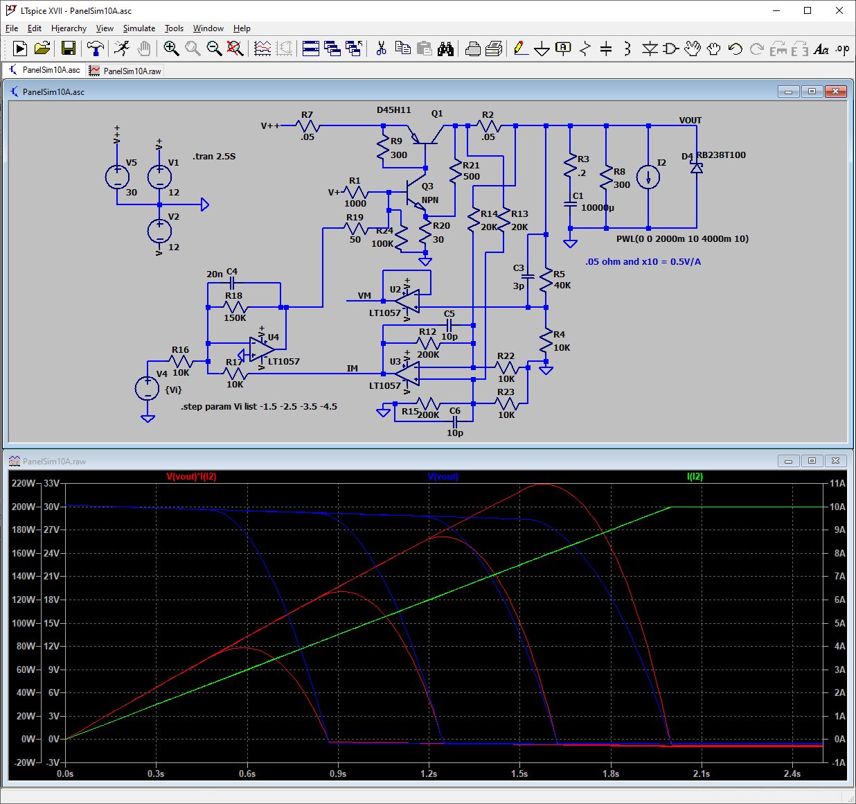
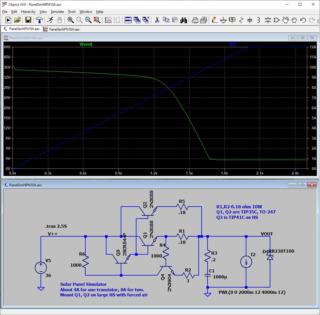
Here is a LTSpice simulation of a Solar panel simulator. At least
in Spice it looks good :-). It uses a LDO PNP stage that I
developed for the Triple Power Supply. The high-side current sense
uses a diff amp, and has imperfect common mode rejection. Using
0.1% resistors for the 10K, 100K and 20K values will help.
Some of the resistors are higher power: R7 and R2 dissipate 5W at
10A, and so are are 10 or 25W chassis mount. Q1 dissipates about
30W at the maximum power point. R30 dissipates about 3W (9V,
300mA) so should be 5W or more. R21 is 30V so about 1W
dissipation. Use a 3W. Q3 is 20V * .3A so about 6W. It should be a
TO-220 mounted the the heat sink. The heat sink will see about 50W
total. It should be large and have a fan. Q1 should be a TO-247 or
TO-3. If the output is shorted to GND, the power of Q1 can get
very high.
The
max current is controlled by V4. The negative slope of the V curve
is controlled by the current feedback gain, R18.
Here is V4 stepped through 4 different values to set the max
current and therefore the max power. Pretty good.
I didn't feel like building a big breadboard or a PC board
for a one-off, so I tried for something simpler:
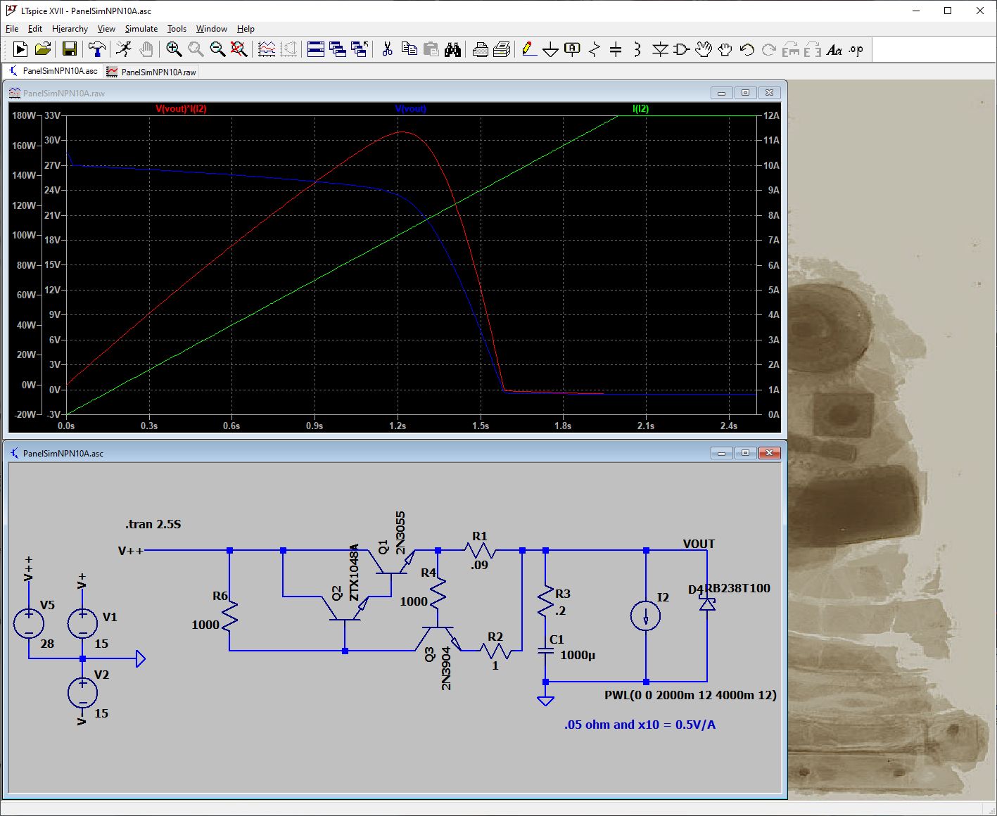
Here is a much simpler circuit. It uses a single transistor to
sense the current. I built it and it works, but initially the
inverter would not stabilize, I thought that maybe the cutoff
slope was to steep. Turns out the inverter won't stabilize unless
the Vin is > ~25V. I initially used a 28V power supply turned
up to about 31V. After current limit the voltage drops to about
24V, not enough for the inverter. I tried a 36V power supply (24V
250W in series with a 12V 250W) and it works fine. The inverter
finds the maximum power point at both 4A and 8A. But even at 4A
the power transistor gets very hot. 10V drop at 4A runs about 100C
temperature with a TO-3 transistor on a medium sized finned heat
sink (12x8cm). Definitely need a fan, larger heat sink, and more
than 1 transistor for 8A. At 8A with a single transistor, the
transistor shorted out. I have some old TO-3 transistors,
but these are hard to mount on a flat heat sink. I'm thinking 2
modern TO-247 transistors on a large, air-cooled heat sink. TIP35C look
line a good candidate. 140W power, low cost. The TO-220
driver transistor and the power resistors will mount to the heat
sink.
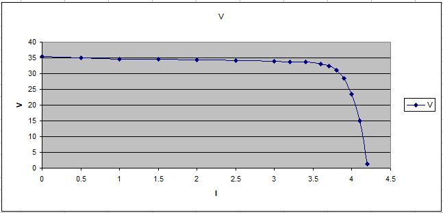
Here is the measured output of a 4A (single 0.18 ohm resistor).
The transistors I used are TIP41C for the driver, and a single
2N3773. Since TO3's are a pain to install and wire, I suggest two
TIP35C in TO-247, and to run each one at 5A or less.
To vary the
power, you can use either a single or two transistors.To reduce the
current from 8A to 4A, turn off Q2. This can be done with a
low-current SPDT switch by switching the base of Q2 from the
driver to its own emitter.
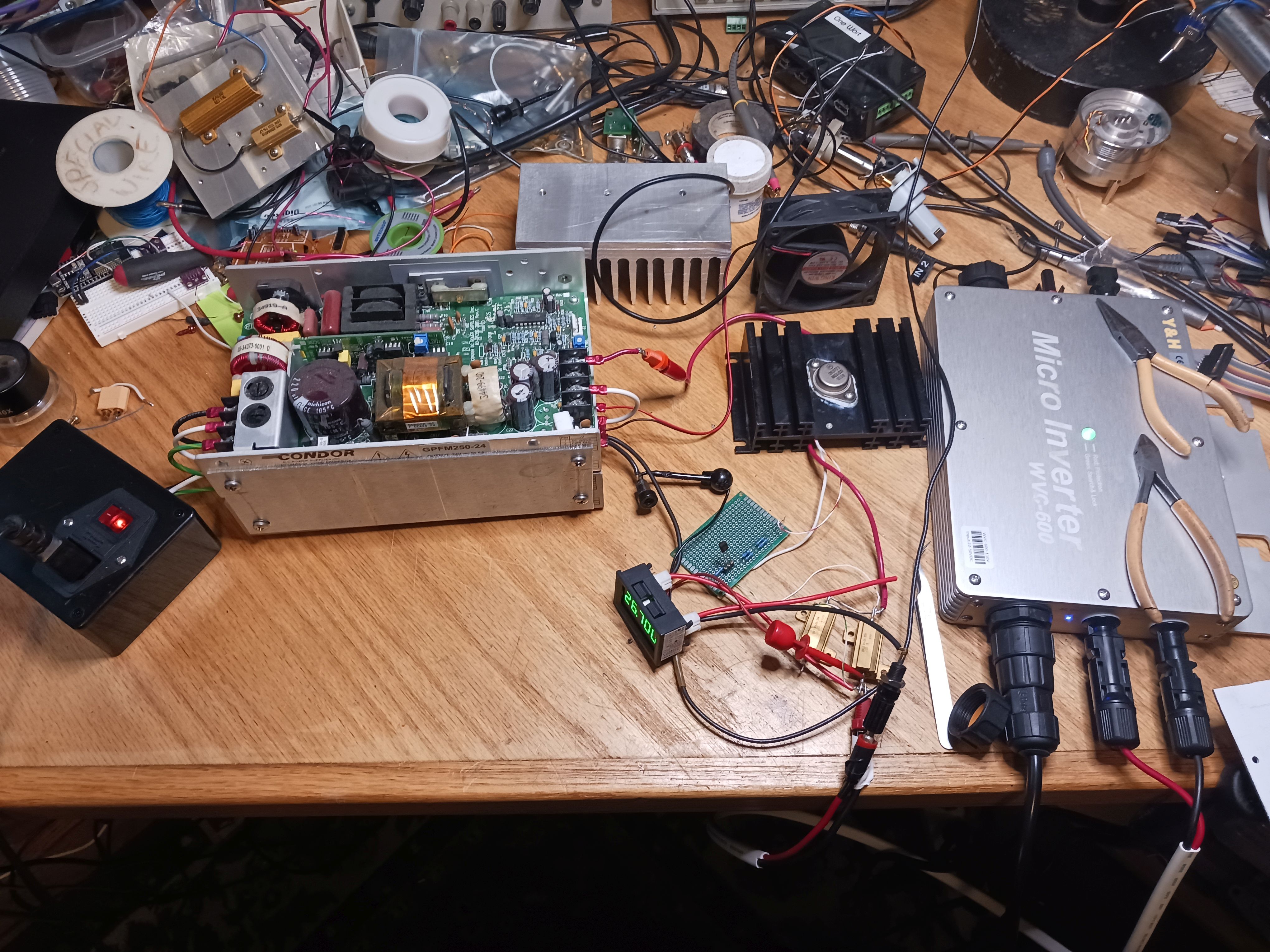
Here is the messy prototype using a single power transistor. The
36V supply consists of a 12V 250W and a 24V 250W power supplies
stacked and wired in series. The TO3 heat sink has a 2N3773
transistor and a TIP41C driver transistor on the back. The two
power resistors are 0.18 ohm 25W. The small breadboard has the
2N3904 and the two 1K resistors. A low-cost panel meter indicates
the voltage and current up to 32V and 10A. The beefy
silver heat sink is for when I get some modern TO-247 transistors.
The fan runs off the 12V power supply.
Ideally
I'd use a 48V 10A supply instead of these old, non-enclosed ones.
They
are pretty cheap. I'd need to find 12V for the panel meter and
fan.
Dave's Home Page
Last
Updated: 10/20/2023