Martin has an old amp. Mine was designed and built by me
in 1978 and I've been listening to it ever since. Reading Randy
Slone's books got Martin and I on the bug of building new amplifiers.
We needed something to drive these nice new speakers. But we decided to
build the speakers first.
I went on the quest for the holy grail of a perfect crossover. First
order crossovers are nearly perfectly flat in the crossover
region, and simple. But their 6db per octave slope cause significant
energy to go to the
wrong speaker. Also their response is dependent on the speaker
impedance
which is not a nice simple number, especially at the frequencies where
you want to cross over. OK, then second order. But when you do a design
for a second order, you find that they are electronically nasty. If the
two
speakers are wired in phase, then a very nasty notch, like -20db at the
crossover results from the phase shifts. The standard fix for this is
to swap the tweeter polarity, but this causes a less objectionable but
still ugly +3db bump.
Third order? At this point the design gets complicated for passive
crossovers, the component
tolerances are more critical, etc.
Martin and I had discussed bi-amping the speakers and using an active
crossover. I decided to design a crossover that would allow the sum of
the woofer and tweeter to be nearly perfectly flat. My first idea was
to build a 2nd order low pass filter and subtract the low pass signal
from the input to make the high pass. This works and it does generate a
perfectly flat sum response, but when you plot the high pass response,
it is only +6db / octave: first order. Not enough slope. Randy Slone's
book has a "phase linear" crossover. It works similar to my idea, but
fixes the high pass response by adding an all-pass stage to correct the
phase. I simulated it with Pspice, and sure enough, it works. But
change any component from it's ideal value by just 1-2% and the
frequency response goes to hell. My original circuit had the same
problem. Very sensitive to component tolerance.
Then I heard about the LinkWitz-Riley 4th order crossover, which is
simply two cascaded butterworth filters each for high and low pass. I
found the circuit on the web and Spiced it up and sure enough, the sum
of the two output responses is beautifully flat. The design is very
insensitive to component tolerance. WIth 5% caps and 1% resistors it
performs very well. Here's the schematic
in .PDF. It is for a either two or
three way, but for now I just built up the two way, using just the
2.5KHz filters. An ExpressPCB circuit board is in the works so don't
build it yet without careful checking. I was able
to squeeze two channels onto their 3.8" x 2.5" mini-board. Here
are the ExpressPCB files for the schematic
and PCB. A BOM is comng.
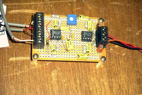
Here it is built up on a little Radio Shack breadboard. It works swell.
Audio in and low and high pass outs are on the left, +/- 12V DC power
is on
the right. The op-amps are nice and quiet, low distortion NE5532s, and
the trimpot is the tweeter level adjustment. Quiet is real important
because this crossover goes directly to the amplifier input. Any noise
will be audible when the volume is set low.
The only trick is that some capacitors need to be a 2:1 ratio, and
there
are no standard cap values that are exactly 2:1. You can put two in
parallel for the 2X values (there are only 2 in the low-pass stages) or
you can do what I did and use 0.047uF and 0.1uF caps which are close to
2:1 (6% off), and select the values with a C-meter to get them closer.
Pick the high 0.047s and the low 0.01s. To check the flatness of any
crossover, tie two equal value (like 1K 1%) resistors from the two
outputs to each other, and monitor the node between the resistors. You
should measure a constant voltage (flat) when you sweep an audio
generator across the crossover frequency. This circuit was flat to a
lovely 0.1db. This trick also works with passive crossovers and
in
Spice to see if your crossovers are flat.
For a bass-midrange crossover of close to 500Hz, you can use 0.033uF
and 0.068uFcaps. This is also very close to 2:1 (3% off). Since you can
get 1% resistors in any values, keep the caps the same and change the
resistor values to tweak the frequencies.
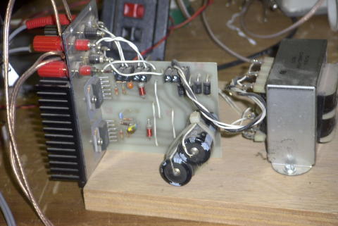
For a test amplifier I used an old 30W / channel amp I built a while
ago. It uses the National LM2876 amplifiers.
For the final speakers we'll use the improved and higher power LM388s
for amplifiers. We'll use one per woofer and one for the tweeter, each
at about 60W per driver or 150+ watts per channel total.