Triple
Power Supply Project: Just a proposal / prototype for now
Introduction
Here are my design notes for a small and simple,
triple, lab power supply. The design uses an off-the-shelf and
low-cost switching +5V, +/- 15V power supply. The outputs
are adjusted a bit high (+/- 16V, +5.8V) to provide headroom
for the pass transistors and the current shunt resistors: +6V, +/-
16V. Then the three regulators are designed for low drop-out (LDO)
to supply 0 to +5V and +/- 15V. They would share a common ground.
But the whole supply should be isolated.
Basic requirements:
+5V 3-4A
+15V 2A
-15V 1A
The three supplied share a common ground.
Separate Isolated grounds is expensive
The common ground is isolated from Chassis
ground.
Use LDO PNP transistors for efficiency and
to maximize output voltage range
Use low-cost, triple switching power supply
for raw power: Meanwell RT65C
Current and
voltage controls
OLED display
Controls: encoder knob and a few buttons
Processor for 12b ADC, Arduino compatible
Fully isolated control via USB with SCPI
(option)
Current status
I need a good LDO regulator design to make this
happen. I worked on a design using PNP transistor for the +
regulators, NPN for the - side. It simulated and tested nice. I
did some initial tests using a MeanWell power supply, it works OK.
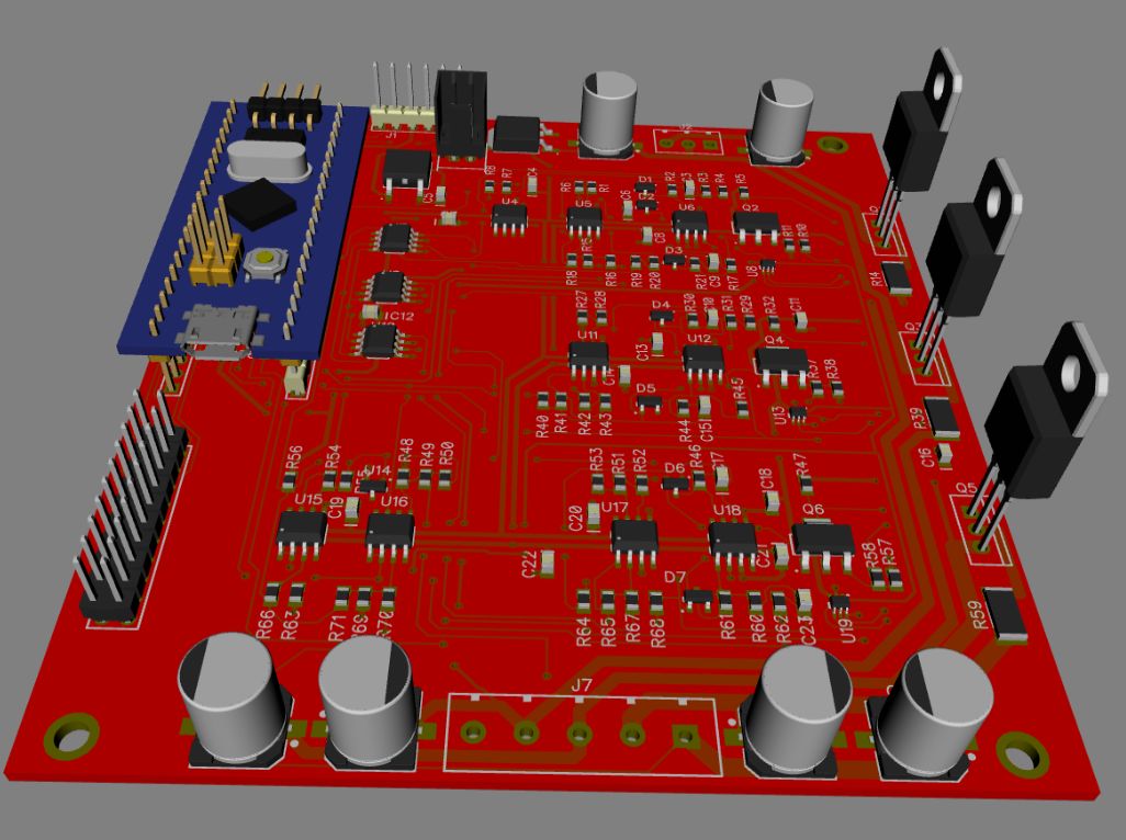
I began the board schematic and PCB layouts, which are about 80%
complete. It shows a Blue Pill CPU which I like for the
performance and cost, but has development issues. R-PI Pico is
another good candidate, depending on its ADC performance. I can
always fall back to a Teensy LC.
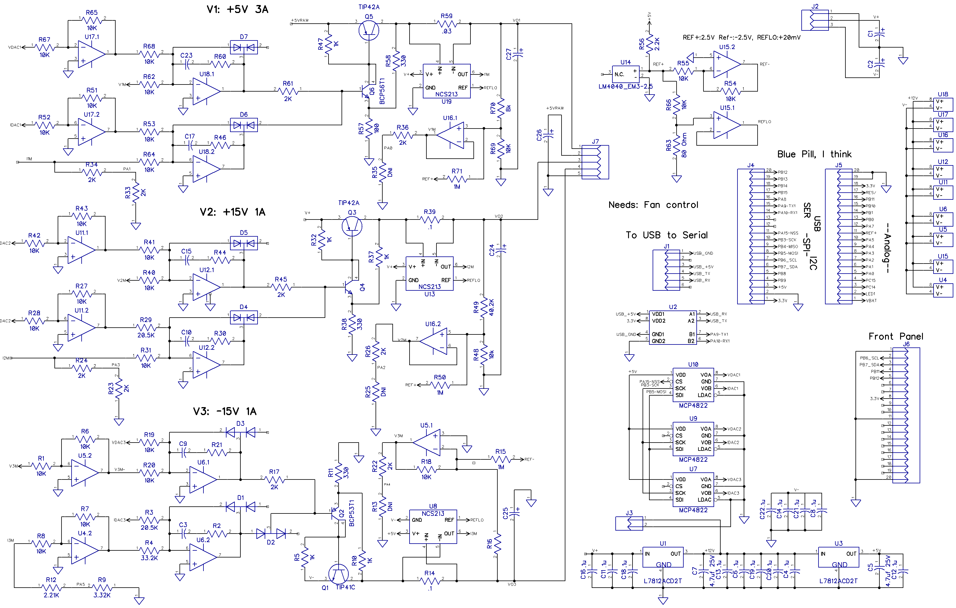
Here is the preliminary schematic.
Design Notes: LDO power stage
I worked on the LDO power stage for a while. I
haven't seen a similar design anywhere. Most linear positive
supplies use NPN transistors. These require a transistor voltage
drop in addition to some biasing drop, so usually 1.5 to 2V
minimum, not counting the current shunt drop. Using a PNP
transistor is appealing because it can be driven almost to
saturation, so less than 0.5V drop. And its base drive doesn't
require more voltage, the base drive comes from ground.
One problem with a PNP output stage is that its voltage gain is
load dependent. So stability and step response over a wide range
of loads is tricky.
Another problem with PNP output stages is that when driving a
capacitive load, the PNP's collector looks like a current source,
and when driving a capacitive load, a large pole in the control
loop is introduced. So the step response can be sluggish. I came
up with a way to lower the PNP's output impedance and stabilize
the voltage gain by adding local voltage feedback. This simple
circuit uses a second, lower power transistor in a common emitter
configuration to drive the PNP. But, you say, doesn't two cascaded
common-emitter stages make for very high and poorly controlled
voltage gain? Yes, but the local voltage feedback lowers the
voltage gain to a reasonable and well controlled x3 to x5.
Check out Q4 driving Q3, with voltage feedback provided by R58 and
emitter resistor R57. Loop gain is 1+ (R58/R17) = 1+ 1K/330 =
4.0. It has the added advantage that R58/R57 also act as a
load to discharge the output capacitors and bring the power supply
voltage down faster. The base of Q4 is a convenient place to drive
the ouptut stage from an op-amp. to get 0 to +15V, you drive Q4
with 15V / 4 or about 0 to +5V.
To make the negative supply, the polarity of the transistors are
reversed.
Design Notes: Cost
The MeanWell power supply is about $25, the board
and parts about $40, and the case would be about $30 for a ~$100
BOM.
Debbie Downer: Reality check
I hate to be a downer, but designing and building
a DIY Lab power supply is hard work and for not much benefit.
There are excellent power supplies and modules available for
cheap. But I need to design and get right:
Enclosure: Must be cheap, minimal hand
work, good labeling, just the right size...
Electronics: that is the easy part. Still a
fair amount of work.
Thermal Design: Low volume and large heat
sinks are always a compromise: too big, too small, wrong
shape, too expensive.
Front panel Controls and UI: Status LEDs,
lots of niggling details.
SCPI Control SW, Test applications,
Calibration, protection circuits, fan control... lots of
details and work.
And when you get everything done and done right,
you have yet another small Lab power supply: not too exciting.
That does not mean I won't do it, it's just not currently a
priority with everything else going on....
Random Design Notes
Common Ground, uses +5V, +/- 15V CUI, MeanWell,
orTDK-Lambda CUT35
$22, 50W qty. 1
Adjust output to +5.5-6 V, +/- 17V
- Supply has a '7915 negative voltage
regulator: Requires removing and bypassing it.
+5V 3-4A
+15V 2A
-15V 1A
Single board has 3 channels, 3 TO-220 pass
transistors: TIP41/42
Controller board module mounted on Main Board
Uses CPU 12b ADC for measure channels
Connections to Front Panel Board
OLED
Encoder
Processor
Front panel jacks
Current sense for +5V and +15V
ON Semi NCS199 100dB or NCS213 100db CMRR,
0 to 26V VIN
$.50
Av
= 50 so .1V -> 5V for ADC
Output bias ~+0.1V to compensate for diff amp, ADC and DAC
offsets
Need V- current sense design
3x V and I, 6x 12b DACs or S/H?
Use STM32 Arduino with 12b DACs? 12b ADC
Use MCP4822 DACs? $2.30 q100. Need 3x2 DACs
Found MCP48cx22 which is < $2, 10 pin
SSOP, EEPROM version avail...
But initializes to mid-scale. MCP4822
initializes to hI-z
S/H DACs cannot hold when processor not
running! Maybe decay to 0?
Blue Pill is STM32F103, has no DAC
$6 from Amazon, $1.5 from Ali Express
Requires external serial programmer or
ST-Link
Serial is good for isolation: only need 2
isolators
Make USB an optional plug-in using a USB
serial board?
Need a good panel mount USB-serial. Build
one??
Blue Pill has no EEPROM, can Flash be used
for Cal?
No. Need other EEPROM.
With ~1000 averages, ADC works well:
~10,000 noise-free counts
CPU
See lab notebook P50... for notes on Meanwell, Blue pill...
When I started this in 2019, BluePill seemed like a good choice. I
bought a few, and there was no cheaper Arduino compatible ARM
processor. Then reality set in. There is no good USB programming
for it, and no USB serial port or EEPROM. These are pretty
fundamental neeeds.
Use Black
pill instead?
Maybe ESP32? Free WiFi and Bluetooth. Not great ADC though
Or Teensy LC for $12, kind-of expensive.
Isolated CPU: probably isolate one serial port for SCPI and
Debug, and be careful during programming via USB
Needs a decent 6 channel, 12b ADC
Use I2C for OLED
Use SPI for DACs
Preferably ~$5-10 for a module with 30-40
pins
* Designed buffer inverter, with feedback. Feedback
helps.
* Simulated V loop with PNP, various loads.
* Needs R-C on integrator
Needs a load for no-load condition
* Proto OLED, use I2C: less wires, fast enough (30mS
update)
Design tasks Finish PCB:
USB
SPI, 3x SS/
FP connectors
Mounting hole locations.
Remote sense 3p conn? It ain't a church.
Fan
FP PCB 4 x 2"
I2C OLED
Encoder + SW
6-7 buttons
V1, V2, V3, < >
LEDs: R/G: V GRN, Ilim RED?
Mounting
Case drawings, 3D CAD
Heat sink design, sourcing
Build Cases: need cooling holes
Build Heat Sink
SPI Code
UI Code
USB Code: serial commands
Calibration Code: I, V, meas. and set,
Offset and gain. Icmrr
I CMRR Code: Im, Iset
Meanwell RT65C power supply.
Looks OK
+5V adjustable up to 5.80V, Could use 6.0V
+15V tracks +5V well: increasing +5V increases
+15V
-15V is -15.02V Uses 7815 linear regulator.
Removed regulator, connected
pins 1-2 -17V
-15 is good for about 1A.
Nice
Need to change V resistor if > 5.8V is
needed
Common mode V is pretty terrible: 8V p-p into
10 ohms !?! Maybe add SMT cap
Bought RT50C, lower power, same size as RT65C
Look at Lambda/TDK CUT35.
Lower power, open frame, $43, may be cleaner and require less mods
Built proto
Measured NCS213R: 109dB CMRR. Spec is 120dB
typ, 100dB min. Pretty consistent but drifts with temp.
Good CMRR is real important for high-side
current monitoring
Looks like a CMRR I offset correction as a
function of V would be pretty easy to do in SW
No load, set V low, set V
high, pretty linear
BUT: Need to correct ISet on
the fly as well. Kinda ugly
Need low-Z +0.02V reference for offsets
Need a design for V- monitoring
Gain of output amp with NPN driver, PNP TIP42
output works well.
1-5V input for 0-15V output,
2A
Simulation:
I and V works
Did V- supply simulation, works.
Ordered Blue Pill STM32F103 board from Amazon
Have 2 FT232 serial boards for programming, but
just using for serial port.
ST-Link download working, no serial boot-loader
yet
ADCs work well >12b
Need SPI and SPI OLED
Had trouble with SPI oled, and it uses many
wires. Using I2C and it works well.
Blue pill links
Has OLED working:
https://squonk42.wordpress.com/2016/11/12/stm32f103c8t6-boards-blue-pill-or-red-pill/
Nice little breadboard power supply:
https://hackaday.com/2019/04/20/a-breadboard-power-supply-thats-more-universal-than-most/
Enclosures
Hammond 1402F 7 x 10 x 3, $66 q1, kind of expensive, but metal
sides help with heat sinking
Needs front and rear panels: $7 each from PcbWay
Maybe get a 7" long one
Cut on table saw, drill 4 holes for side screws
Build blue pill Leo board??
No, Blue Pill is the devil. Consider Black Pill ($6), Teensy LC
($12) or other CPUs.
7 x 3 FP
Design for ~4" wide? 1/4 Rack is 4.25"
No, board less heat sink is already 4" wide
------------------------
|
-------- |
| | OLED |
|
| | |
O o o | Encoder
|
--------
|
| o o o o
o | Buttons
| o
o o | Status
LEDs
| O O O O
O | 5-way Binding, 0.75" spacing
-----------------------
Front Panel
128 x 64 OLED, 1.3"
3 or 4 ON/OFF buttons
Encoder w/SW
Digit select buttons (2)
3 On/Off LEDs
3 Current limit LEDs?
Or GRN = on V, RED = on + I Limit
UI for Triple PS
1.3" OLED is a bit small for 3x current and voltage readings
Encoder switch goes to next screen:
Main Screen: Status of all:
5.123V 1.234A OFF V
+12.345V 1.234A ON V
-12.345V 1.234A ON V
Encoder switch sets screen
<> selects digits. Field Select?
Ch 1 Set
+12.345V 1.234A Set
+12.347V 1.232A ON V
Ch2 Set
-same-
CH3 Set
-same-
< > selects digit
up.down selects channel and I/V
ON/OFF per channel + ALL
Can timeout to main screen
One screen:
12.345 A
42.123 V
ON/OFF