DIY SMU:
Source Measure Unit Page 2: DIgital
The
Blog for this project
The
Schematics, PCB files, and BOM are here
Page 1: the Analog
part
Page 3: Board Bringup
The Schematics, PCB files, and BOM are
here
Page 3: Board Bringup
Page 4: Board Bringup II
YouTube
Video Chapter 1: DIY-SMU Intro
YouTube Chapter
2: New CPU and Case
YouTube
Chapter 3: New Case and CAD tools
YouTube Video 4: Instrument Control Via
SCPI
EEVBlog
Forum Page
The digital part of the SMU is fairly
straightforward. Compared to the older instruments based on older
processors, it is significantly smaller and lower cost.
ADC
The 5-6 digit ADCs on many commercial instruments
are often multi-slope designs typically using a discrete analog
front end and either a microprocessor or programmable logic for
the digital part. There are many ADCs
on the market. These perform well and are very small. Delta-Sigma
parts offer good performance as well as flexibility in trading off
accuracy vs speed. Most use an SPI interface which makes
isolation straightforward. Requirements:
- 24 bits, bipolar input, single ended
(pseudo-differential)
- ppm drift and non-linearity
- 4 wire SPI: CK, MISO, MOSI, SS/
- 2 or 3 channel Mux
- ~1KHz 20 bits performance, able to tradeoff
speed vs. bits
- 5V Vdd input range
- Human solder-able package
The AD7190/7193 parts look good. The AD7190 has 4
pseudo-diff inputs where the - input can be biased to the
reference voltage for bipolar operation. Perfect. Some more modern
parts are 3V only, but the '7190 can be either. To use a 5V
or 3V part, the input will probably need to be buffered by a
precision, low-voltage RRIO op-amp such as the TLC2272.
DAC
The original 236 used two 14b DACs, with external
serial to parallel registers, and current to voltage amplifiers.
Lots of giant DIP parts. I plan to use a single tiny 16b 4-channel
DAC with low INL errors. It too is SPI.
Main Processor
The processor requirements are
straightforward.
- ~256K bytes Flash (program) memory
- 128K RAM
- USB Device interface
- Serial emulation for instrument control
- Used for device programming and debug
- EEPROM for calibration factor storage
- SD Card would be nice, but not absolutely
needed.
- High-resolution color display
- Used for setup, numeric and graph
display.
- SPI
- Touch screen would be nice
- Leaning towards 480 x 320 landscape TFT
with touch screen
- Need high level graphics library.
LittleGL?
- Looking at Nextion smart displays.
- Controls:
- Buttons for major modes:
- Encoder for menu and selection
- Encoder to set values:
- Digit selection buttons: <, >
- Encoder button
- SPI Interface for Instrument
- Isolated on the instrument board
- 3-4 select lines: ADC, DAC, GPIO
- Compliance input
- +12V input voltage
- Regulators for +5V, +3.3V
- +5V and +12V to the analog board.
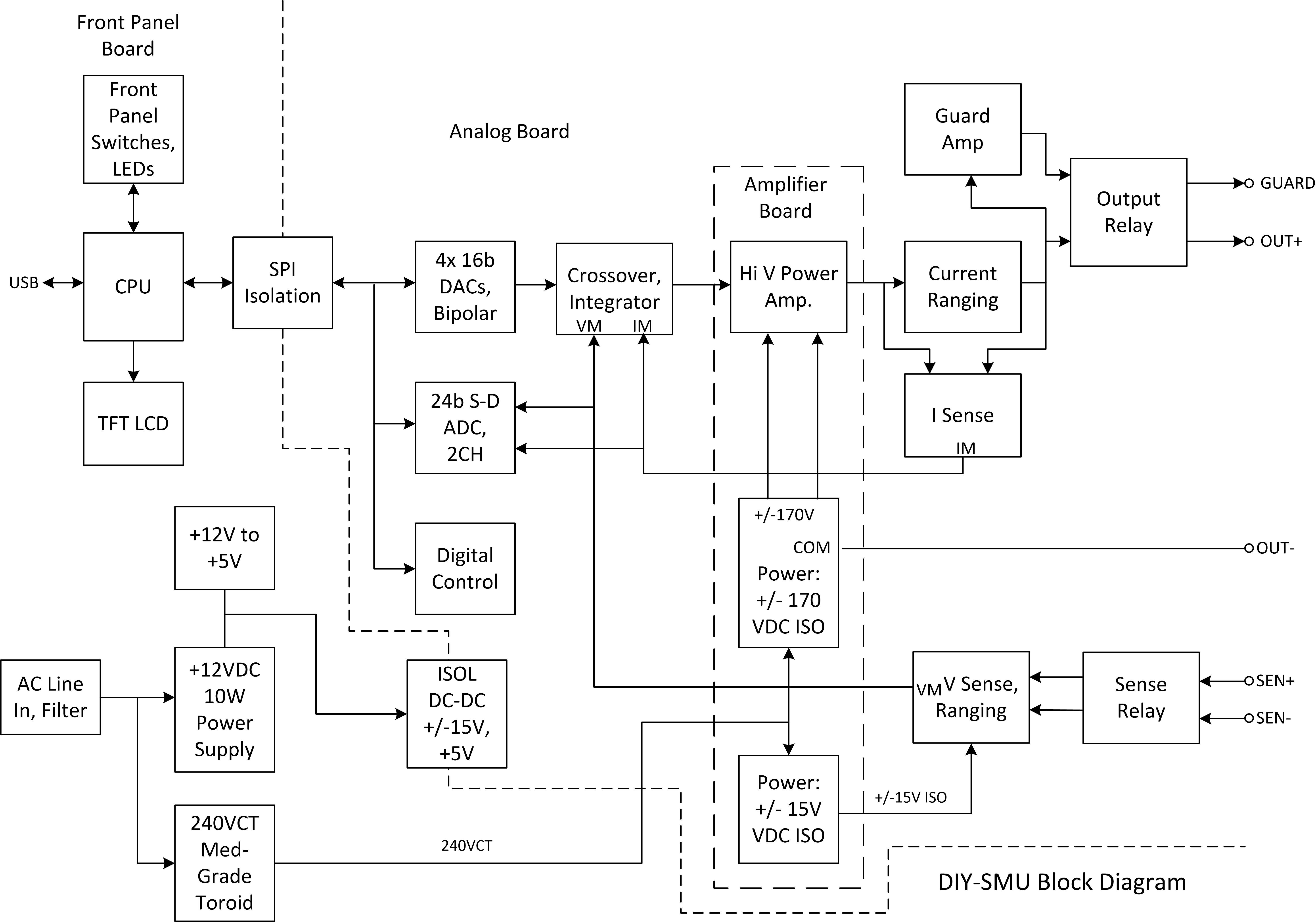
Here is the block diagram for the system. The
digital parts are on the left.
I am a fan of Teensy processors having used them on several
project. The processing, I/O speed, and I/O needs for this project
are not much. The ADC operates at a maximum of about 4KS or 250uS.
The LCD has the highest demands to keep up with user inputs and
perform real-time data display. A 480x320x16b display has
307KB of display memory. A single Teensy 3.x or 4.x should
do the job.
Since a front panel board with LCD and controls is needed and
these use most of the I/O, the processor module should probably be
mounted to the back of this board. A single 14-pin ribbon cable
can provide SPI and power to he analog board. An internal USB
cable can connect the Teensy Micro B to a rear panel USB-B
connector.
For the initial bring-up, I'll use one of my LeoLed controllers. This is an
Arduino Leonardo 8 bit processor with a small OLED display, an
encoder, and a few buttons.
Nice Buttons
Having nice buttons with labels is a challenge
for DIY projects. I haven't figured out how to make them. Hmmmm.
GUI Software
- Main screen
- Modes, Ranges
- I and V force and measure readings
- Encoder to set values
- Plot Screen
- Time plots of Measure data
- Button and encoders for X,Y offset and
gain
- X/Y measure vs. force plots
Page
1: the Analog part
Page 3: Board Bringup
Dave's
Home Page
Last Updated:
10/14/2022