PC Preamp Project
By Dave
Erickson
I looked for the ideal PC to audio interface and was unable to locate an off-the-shelf solution. It should have tone controls including volume, balance and loudness compensation. It needs a high quality headphone output (high power, low noise and distortion, good impedance match) for 1/4 “ and 1/8” headphones. It needs a balanced line level output to drive a remote stereo as well as a balanced line-level input from a remote stereo. Balanced is needed to eliminate ground loops.
I
also looked at WiFi and networked PC interfaces. These solve the PC to
stereo problem and the ground loop problem. But they do not provide the
return signal (stereo to PC), and also I suspect that they don't lend
themselves to listening to the same material local to the PC and froma
stereo. If they do, then they would require a short delay to the
stereo. Ever listen to two channels of audio with a delay? This doesn't
enhance the listening experience. I have a house-wide stereo and can
play the same or different sources at several points in and out of the
house.
It should have a high quality phono preamp to allow ripping vinyl to the PC line input. A selector switch to pick the sound source.
In addition, a 25-35 watt per channel amplifier to allow quality speakers to be used. THis can be bypassed so active speakers can be used.
Here are the requirements in outline form:
Preamp:
Headphone amplifier:
Stereo Connections:
Amplifier:
Size:
For a
phono preamp, I
have a lovely board I
built in the late 70’s. I owned an Advent 300 receiver
at the time. This minimalist receiver uses a Holman designed
phono
preamp. The bipolar transistor design uses 6 transistors per
stage instead of the usual 2. It sports a differential input
configured as a current source loaded high gain stage, followed by a
darlington X10 voltage
amplifier, followed by a 2 pole, high
pass filter with emitter follower output for rumble rejection. In 1977
I 'borrowed' the
circuit and laid out a single-sided board for it. A friend and I
built 4
of these boards for use in home stereos and in a disco mixer.
With better components the noise performance was as good or
better better than
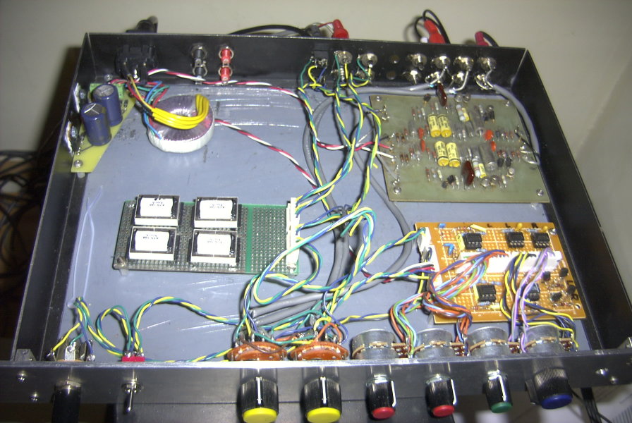
the Advent 300. Fortunately I still have a couple of these
boards and one is now located in the upper right of the PC
Preamp. It still sounds great. I worked at Hewlett Packard
Medical division in Waltham at the time. Many of the parts are from HP
lab stock. I thank HP for their generous lab stock policy.
Here
is the schematic in .PDF for my
version of the Holman preamp. Advent put the original schematic
in the owners
manual and it is now available on-line from various Advent 300 repair
and upgrade web sites so I am not giving away any secrets. I changed
all the original 5% resistors to 1% metal film, and
use tantalum capacitors in place of the original cheap electrolytics.
The Advent 300 upgrade web sites report degradation or failure of the
original circuit due to the electrolytic caps drying out over time.
Also they
used 16V caps on 12V power supplies. This is a bit marginal and
accelerates failure. For best reliability I use tantalum caps which
don't exhibit this problem and perform better in most power supply
circuits. Also I
use 2:1 voltage
derating: 25V
caps in a 12V circuit. The original design used noise selected 2SC1345E
for the NPN differential pair stage I used T0-92 2N5088
transistors for these. These provided a nice low noise level on
the front end. When I A/B tested my design vs. the Advent 300 by
listening
with headphones and the volume cranked up, my noise was a tad
lower. The original circuit used 2N5087s for the PNP constant
current stage. I
used metal can 2N2907s for these. Nowadays I'd use plastic
2N3906s for the PNPs. Holman used a darlington PNP MPSA65 for the
voltage amp
stage. I used two PNPs for that stage. For simplicity I used the same
2N5088 NPNs on
the emitter follower output stage. The original design used
non-noise-selected 2SC1345Es here. They had to use the rejects
somewhere.
The PC artwork is an ancient hand-taped (pre-CAD), single sided desgn which I cannot readily publish since the artwork is long gone. The layout is not particularly critical as long as you keep signals short, flow from the inputs at one end to the outputs at the other, keep the power traces away from the inputs, and run a nice fat ground trace down the middle, between the channels. An ExpressPCB mini board would do this circuit very nicely. I laid one of the two channels but no the other. The other channel is a mirror image except for the transistors and power inputs, so be careful. This layout has not been checked for cap sizes, etc, so use at your own risk. Here are the ExpressPCB Schematic and PC layout. The software to edit them is at ExpressPCB.
When coupling a PC to a stereo, one should be careful to avoid ground loops. A ground loop will generally cause annoying 60Hz hum in your speakers. They are caused by connecting two pieces of equipment with single ended cables when there is also a power ground or 3 wire power cable on each equipment. The house ground wiring causes small amounts of AC voltage to between the grounds of two pieces of equipment. Then when an audio cable is connected, that voltage induces a current in the audio ground lead ( the shield ) which induces a voltage at the equipment input. A decent stereo wants to see less than -80db of hum or about 100uV on a 1V signal. This is nearly impossible to achieve in the presence of a ground loop.
For consumer audio gear, single ended line-level audio on RCA jacks works OK as long as the system is simple enough and most of the system uses 2-wire line cords and decent power transformers. This is the case with most home audio gear. It’s when you hook up a PC or video equipment that ground loops can occur. It is very likely that a PC chassis and its I/O connectors are grounded, even a laptop that uses a 3 wire power adapter. It is also very likely that the stereo has a chassis ground or 3 wire line cord somewhere. Some stereo systems are entirely 2 wire, but sneak ground paths through a cable box RF shield are common. In any case, balanced inputs and outputs eliminate the ground loops. If you have ever tried to trace down a ground loop and the stereo are grounded somewhere you will know the pain. Planning for them in advance is good.
There are a couple of ways to reduce ground loops when passing audio from equipment to equipment. Differential inputs with good common-mode rejection will do it. The problem with this approach is that an unbalanced line output often will have two different impedances in its ground path (near 0 ohms) and its signal path: typically 100 to 1,000 ohms. So to get 80db of CMRR with this approach, the input impedance must be 80 dB or 10,000 x the difference in impedance or 10,000 x 1,000 = 10M ohms. It is hard to build such an amplifier. It requires clever bootstrapping, precision matched resistors, trims, or worse. The other solution is to use audio transformers. Unfortunately these generally need to be shielded, and high quality audio transformers are in the $50 and up price range. You need 4 to receive and send stereo. They are large and heavy.
For coupling transformers, I have previously used 600:600 ohm modem transformers with good success. Most modem transformers are only specified for about 400 Hz to about 5KHz, but have actual response far beyond. The challenge is in the low frequencies: a transformer that can handle 20Hz full amplitude sine waves is hard to find. It would seem impossible to find a transformer that is specified for 400Hz but can pass 20Hz well, but there is a loophole. Many modem transformers are designed to pass about 50mA of DC current on the telephone line. This requires a larger core and heavier wire that can avoid saturation while still passing the 400Hz. So most transformers designed for DC can pass 50Hz at 1.0V p-p and some can pass 20Hz without the DC.
At the high frequency
end, all the modem transformers I have
tested passed up to 25 KHz before cutoff. As far as shielding, I have
used them unshielded within 6" of a CRT monitor without hearing adverse
effects. They do pick up hum if they are not driven by a low impedance
though. But when there is sound there is drive. These particular
transformers are Atech ATS-166, purchased
from surplus dealer All
Electronics
for $1 each. All Electronics used to have other
Atech models available but they distort on 20Hz test signals at 1V p-p.
The
ATS166 is by far the best $1 audio transformer I have found. Seriously,
they work very well.
As
far as driving and receiving impedance, they work well with a low
impedance drive (0 to 200 Ohms) and a load impedance of 1K Ohms or
greater. Get a couple, test their frequency response. Stick them
between any line-out / line in and have a listen. I think you'll be
impressed.
Here is the schematic for
the other boards, the
switching and the connectors in
.pdf. Here is the original file in
.SCH format for ExpressPCB.
Download
their excellent free software to edit it.
The tone circuit is a classic treble and bass
Baxandall
circuit built with the excellent NE5532 audio Op-amp. Like most active
filters, this is succeptible to source impedance, so
a unity gain buffer stage precedes it to provide a low source
impedance. Since the tone circuit uses an inverting
configuration and I want all output signals to be non-inverting, the
balance circuit re-inverts the signal. I generally prefer to have the
volume control last in the signal chain. That way when the volume is
reduced, any noise from the previous stages is also reduced. But this
application requires a low impedance output driver after the volume to
drive up to three amplifiers: the headphone amp, the external powered
speakers, and the main amplifier.
For
loudness compensation, there are simpler circuits but they typically
require a tap on the volume control. This one is pretty reasonable. I
DC couple its input and output and then AC couple only after the
balance stage. The DC bias errors accumulate for the tone, balance and
volume circuits. Worse they are a function of the Bass, Volume,
Loundness and Balance controls. Then all magically fixed by the AC
coupling cap at the output. The problem is that this 100mV or so of DC
has an unknown polarity. So the 4.7uF coupling cap should be
non-polarized. So much for using a tantalum. Could use two 10 uf
tantalums in series, back to back. Could use a film cap (big and
expensive). Could use a NPO electrolytic. I use a 4.7uf tantalum and
figure it can handle 100mV of reverse polarity.
For convenience, the headphone amp
circuit
is mounted on the tone board. It consists of my favorite NE5532
wired as a X4 non-inverting amplifier with a discrete, complimentary
emitter follower stage to boost the drive current. The follower uses 3
diode drops (2.1V) to bias 2 transistor Vbe junctions plus two 33
ohm resistors. So the 66 ohms of resistors have 0.7V across them
causing a bias current of ~10mA to flow. This is enough to reduce
crossover distortion to a very low level. This circuit will drive a
nice clean 0.5 watt into 50 ohm headphones so be careful with the
volume adjust else you may damage your hearing.
The current limt is a simple 47 ohm resistor in series with
the output. Crude but effective. The 47 ohms also isolates the
amplifier output from capacitive loading caused by long headphone
cables. It's a good idea to add a resistor to any audio line output for
this reason.
Since this project will live in my computer
room, I wanted a decent looking package to hang from the shelf above my
PC monitor. I like the idea of 1U rack size (1.75"), and this provided
space
for all the circuitry, controls and I/O. The enclosure is 10"
deep x 15" wide, and has room for an external heat sink along
the left side. It will mount via the rack ears on simple angle brackets
with 2 screws. The rear will be supported by a bracket. This same size
package could be used under a monitor as well.
For construction I used sheet and angle
aluminum. Home Depot has 2" x 2" lightweight (0.060") angle bracket. I
cut this down to 1.7" x 0.25" for the sides and back. The front is a 1
3/4" (1U), 1/8" aluminum panel. These can be purchased in a nice
brushed aluminum, black anodized finish. I chose basic sheet metal and
have not decided how to finish it yet. The bottom and top are 0.060
aluminum. To mount the front to the sides and base, I used 1/4" x
1/4" bar stock. Unfortunately I could not locate aluminum so I
used steel. I drilled and tapped holes in it to accept 4-40
hardware. Drilling and tapping steel is no fun. I recommend buying 1/4"
square stock from a local metal vendor or from McMaster Carr. And to
prevent breaking your 4-40 taps, use a tapping lubricant or at least
3in1 oil.
This approach was a lot of work. In retrospect, next time I
think I will use 1/4" or 5/16" X 1.5" aluminum bar stock for the sides,
and drill and tap it for the front, top and bottom screws.
For
board construction, I used prototype boards where a PC board was not
available. When I need to build more than one of something, ExpressPCB
is the way to go. But for one-offs, hand wiring is fine. I like the
Radio Shack breadboards for building small DIP prototypes. Their
smaller board can take 1-2 DIPs, the larger one was used for the preamp
/ headphone amp board. These can support up to 3 rows of DIPs. I needed
many connections to the front panel controls, so used the center row
for these connectors. I use the Molex / Waldom single row 0.1"
connectors for most board-to-wire connections. These work well
with hand built breadboards and are available in straight and right
angle versions. To build the cables, the pins are crimped on #24
insulated wire and poked into the housings. The Radio Shack crimp tool
works well with these pins.
The
transformer board was made from a scrap of G-10 proto board and
hand-wired. The input and output conections are both 6 pin Molex.
The +/-
12V power supply board is courtesy of my employer. We built this board
because an internet search for a small and simple bipolar linear supply
board came up dry. It is that funny trapezoid shape because it was
built on the scraps of an ExpressPCB mini board from another design.
With ExpressPCB mini boards, all boards are the same size so if you
want a smaller board, you cut off the excess. But the excess can be
used for other board functions and I hate to see it go to waste.
Input
cables are shielded. Output cables are unshielded. As I don't consider
R-L channel separation a real important spec in a stereo. I use three
wire cable everywhere: 2 shielded condustors. In fact I use this stuff
for my 30' PC to stereo runs. Sure, there will be some hight frequency
crosstalk between R and L, but probably not much compared to my head
and ears.
All
boards are mounted on 3/8" 4-40 spacers. The balanced input and
output cables still use RCA jacks, but these are insulated from the
case by plastic shoulder washers.