DIY SMU: Source
Measure Unit Page 5:
Calibration,
More Testing, Applications, Curve Tracer
The Schematics, PCB
files, and BOM are here
Page 1: the Analog part
Page 2: the Digital part
Page 3: Board Bringup
Page 4: Board Bringup 2
EEVBlog
Forum Page
Youtube
Videos
101 uses for an SMU
Having 2 DIY-SMUs on the
bench has been very handy.
High resistance (and
voltage) tester
To build an SMU, the six
power transistors are screwed to the heat sink with insulating
thermal pads and nylon shoulder washers. But they must withstand
over +/- 300V with very low (or no) leakage. 10nA at 150V is 15
Gohms. An insulation tester (which I don't have) is good for this,
but so is a SMU. So after first checking for an open circuit by
measuring the heat sink to Amp GND with a DMM (20Meg ohms and a
few volts max), I use a DIY-SMU set to 150V and the 1uA range, and
look for < 10nA. This works swell.
Christmas light repair
If you have tested an LED
with a power supply, you may be familiar with this scenario:
- Set Power supply to
5V and 50mA
- Connect LED (that
can handle 4V and 50mA)
- Blow the snot out of
the LED with one final, bright flash
- Wonder what went
wrong
What happened is that the
power supply output capacitor, about 100uF was charged to 5V, and
when the LED was connected, the big capacitor dumped all its
stored energy at 5V into the 2-3V LED before the current limit
could kick in. If you turn the power supply off before connecting
the LED, things will go better. It's hot-connecting the LEDs that
caused the damage. An SMU, on the other hand, has a minimum of
output capacitance and so very little stored energy. So you can
hot-connect it to LEDs, and is ideal for testing strings of LEDs.
I recently struggled with repairing a string of LEDs and SMU to
the rescue!
A string of Christmas LEDs typically operates at 120VAC RMS and 10
to 20mA. When one or more bulbs are out, the entire string goes
out. Then your job is to find the bad bulbs. Usually white or blue
LEDs use ~4V and have about 33 in series for a total of 120V.
Connect the AC input to a SMU, set to Force current mode, 150V
range, 10mA. Strings of ~33 LEDs should light. Change the output
to -150V and the other LEDs should light. Once you figure out what
string the bad LEDs are on, remove the middle light from that
string, and apply the correct polarity of the 150V current
source to the pins. If half the LEDs light, then the problem is on
the other half. Then split the remaining half and try again
(binary search, divide and conquer...). Repeat until you find the
fault(s). I was able to repair the lights in a few minutes this
way.
As a supposedly smart EE with a lifetime of experience, I was
always frustrated by my inability to solve this problem. Instead
of fixing the string, I would sometimes cut out the bad section of
lights and bypass it (solder and heat-shrink). Or sometimes I
would toss the string and buy a new one, very unsatisfying.
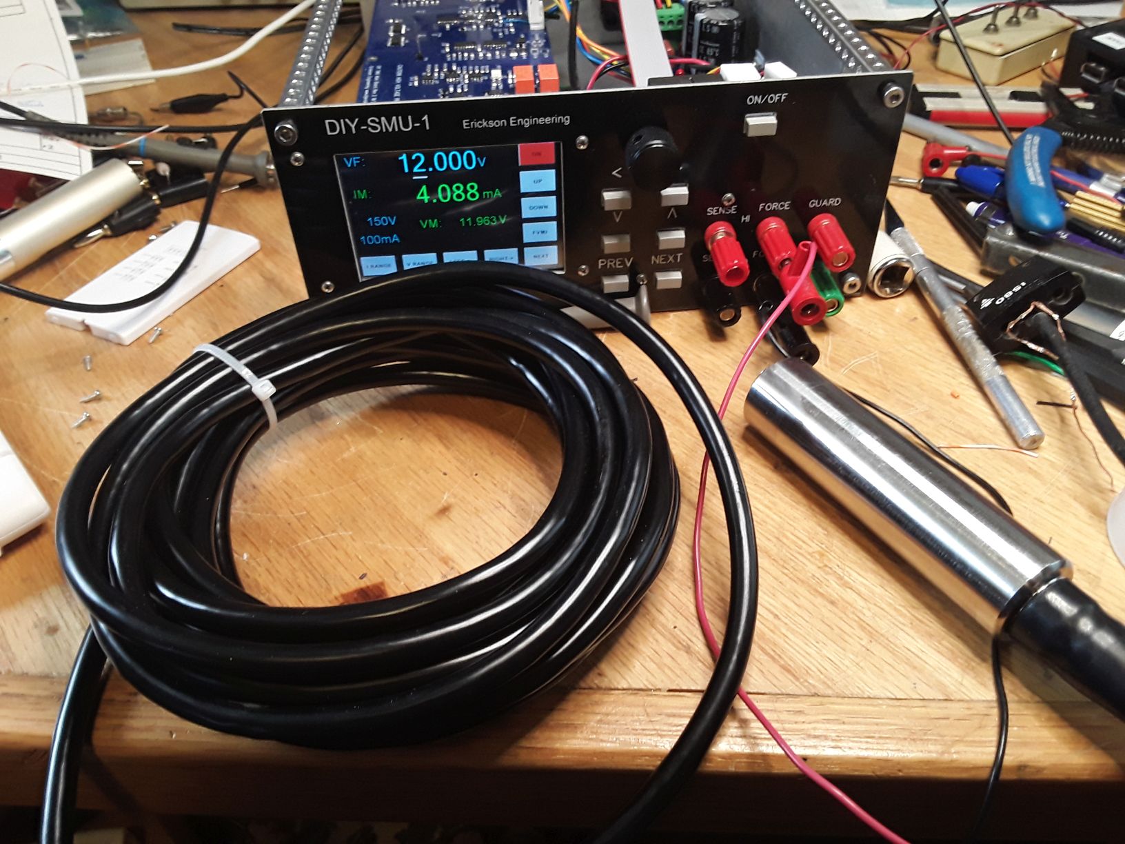
Testing a 4-20mA depth
transducer
A buddy wants to monitor
lake depth at his remote cottage using a water depth transducer,
and I am trying to adapt it to an off-the shelf weather
station. It outputs 4-20mA. Here it is connected to DIY-SMU.
4ma is the output current with 0 depth.
2021-2022 Parts
Shortage Hell!
This is a very tough
time to develop an advanced electronics project. The industry
semiconductor shortages cause a minefield of problems every time
you order boards. Parts that were plentiful 6 months ago, now
have over 1 year lead times. Some key components in DIY-SMU that
are hard to find, super-long lead times, or are unavailable:
- OPAx140 precision
Bifet Opamp. This is (was) the main opamp. I replaced them
with the cheaper, slower, and more available OPAx145 parts.
Same DC specs. 2022 update: these are now hard to get also.
- AD5668 quad 16b DAC
in SSOP16. I found some B grade parts (the good ones) at
Mouser and ordered enough for the next year or so. If you are
interested in building DIY-SMU, I recommend you do the same.
An alternative is to re-lay out the PCB for the QFN package,
but I am reluctant to use QFN's on a DIY project. But if
I get desperate for parts...
- Si8661, 6 channel
(5/1) isolator. I use the lower isolation voltage, narrow
SOIC16 package. The SOIC16W wide packages are more available,
so I changed the Rev2 footprint to accommodate either the wide
or narrow packages, a bit of a hack. One compatible part is
the ADUM261. It uses magnetic coupling instead of capacitive.
I have used the Si8661 in several previous projects: SPI-DAQ,
and 18b DAC, so I have about 8 of these on hand.
- DG444 CMOS Switches.
These are hard to find, but the board can accommodate either
DG444 or the more common DG441s.
- Recom DC-DC: Only
the 3KV High voltage isolation version is available, and only
in small quantities. Other DC-DCs will work but may have
higher noise.
Early 2022, Digikey
showed a few thousand ADUM261 isolators in stock. This solved my
Isolator problem, but I needed to qualify them, so I put 10 in the
shopping cart. A day later when I pushed 'order now', there
were 0 in stock!! There are no 6 channel, 5/1 fast isolators
available anywhere. ADUM261 is showing delivery in January
2022, only 2 months away, so I ordered. A tube of them which
arrived late January 2022. I have not tried one yet but plan to
try them out.
Fortunately the
parts on the Amp and CPU board are common as dirt and readily
available, as are the Nextion LCD and the Teensy 3.2. For
now anyway.
3Q2022 update: I spoke too soon. Teensy 3.2s shipments are way
out. Teensy 4.0 is unavailable but should be in stock
12/2022. Should be an easy change. I hope.
Ordering New PCBs
I am getting ready to
order Rev3 Amp boards and Rev2 main boards. Here are the board
changes:
- Main Board Rev2:
- Improved bypassing
of AD7190 ADC power and reference to improve non-linearity
- Change ADR431 2.5V
Ref. to ADR421 for better capacitive load driving.
- Fix DC-DC noise:
allow either CMRR choke or single inductor
- Change OPAx140s to
OPAx145s: more available, and lower cost solution
- Add amp control
for current ranging
- Change footprint
of isolator to allow SOIC16 N or W due to availability
issues of narrow part
- Bury a few minor
reworks
- Look and other
availability issues
- Amp Board Rev3:
- Add switchable
current limits: 15ma for 10ma and less, 150ma for 100mA
range
The DAC, AD5686 is not
currently available in the high precision version in the SSOP
package. It is available in the lower grade. I thought about
changing to the QFN (leadless) package, or laying out the board
to accept both. The layout in that area is pretty tight, so I
decided to suffer with the lower grade part for now.
New Board Bringup
The new rev boards are
in. I assembled 2 units each of the Amp and Main boards, plus a
new Rev1 CPU board, and one new case. The second new board will
go in an existing case. This brings the number of complete units
up to 3.
The Amp board came
right up. Since it was new artwork I started bringup by powering
it from a +/- 40V DC power supply with current limiting. The
Main board had a problem, no negative output. -15V to the Amp
board was GND by a schematic error. I cut the ground plane
around J2 pin 4, and added a wire (of shame!). Board #3 came
right up after that. Board #4 had a strange problem: The +2.50V
voltage reference worked fine when +12V power was applied, but
when installed in a system, the voltage reference raised to
+3.6V. I thought it must be a short form Ref+ to some digital
signal. Ultimately I replaced the isolator Si8661 which was
drawing excess +5V current on the input side, and the ADR421
reference. Then the board worked fine, but sad since Si8661's
and ARD421s are both on shortage and I only have a few. Both
boards ran voltage calibration nicely.
I wired up a new
(third) chassis, and realized that there is no wiring diagram or
schematic for the chassis. So I made one (above). Also instead
of measuring and drilling the bottom plate, I carefully
measured, marked, and drilled a drill template for the bottom.
Now making bottom plates can be done quickly and easily. I made
one for Unit #3.
I measured the output
noise using the new DC-DC and the common-mode choke circuit, and
they work well. Same ~5mV noise as Rev1.
I noticed that one new
board started up with -150V output voltage for a few seconds
until the firmware set up the hardware and set the DACs and
ranges, and turned off the output relay. This is not good! It
means that some bits of the two 74HC595 control registers were
coming up HI. I have a reset circuit, but according to the
74HC595 data sheet, the reset pin only clears the input shift
register, not the output register. Also when I went to buy the
original NXP devices, there was a shortage, so I bought TI parts
instead. I think that the NXP units act differently, which is
concerning. I need to determine whether the reset behavior is
guaranteed or just a fluke. I'll buy some NXP and find out. Not
a very satisfying solution any time you have to select one
vendor's part....
After ordering NXP
parts and an hour or so of googling "595 reset" and the like, to
find out how others deal with this, I finally found one posting
that said that the '595 with tri-state outputs controlled by /OE
is intended for bus oriented applications. The '594 is a similar
pinout part but with an output reset pin RCLR/ and no tri-state.
Doh! Then why the heck does everyone use the '595?? I can rework
in a '594 by simply lifting pin 13 and connecting it to pin 10.
Another change for Rev3.
Next is to install the
new Amp board and test the high-low fault current limit
settings.
Amplifier Current
Limit Tuning
I discussed on-line the
need for amplifier current limiting when the instrument is in
force current mode and the applied external voltage is outside the
voltage clamp range. In this case, the current is limited only by
the inherent limits of the amplifier which exceed the DG441
maximum currents. When I first did this test, the 10mA DG441 and
current sense resistor (R42, 499 ohms) fried. The design was
waiting for the new rev boards to address this. The Rev2 Amplifier
only had a single +/-150mA current limit. The Rev3 amplifier adds
a FET switch and bias resistors to reduce the current to < 20mA
for the lower current ranges. I also added a bias resistors R24
and R25 to adjust the <20mA current. Without these, the drop
across the 25 ohm current sense resistors is about 20mA * 25 =
0.5V, not enough to turn on the current limit transistors.
I was nervous to apply external voltages outside the voltage clamp
range, but it works well. With the initial components, (R24,R25 =
50K) the current limits for 100mA was 130mA, and for 10mA was
23mA. Not bad, but I want the 10mA current limit to be < 20mA.
I found that the simulation model for the circuit didn't
completely agree with reality. In simulation, the
2N3904/3906 transistors bases conduct with about +/- 0.705V, but
in reality it is about 0.72V. When I changed the 50Ks to 36Ks, the
currents dropped to 18mA / 122mA. This is excellent.
Finally DIY-SMU is a 4 quadrant SMU with protection against faults
on all ranges.
But, but, but... how is 18mA fault current getting through the
high resistance current shunts on the low current ranges? I
traced it through the high current shunt (R40 || R41, 50 ohms) and
into U17-15, its current sense switch, so the DG441 protection
diodes are absorbing it into the +/- 15V power rails. Not good. I
have been hoping to avoid the leakage of added protection diodes
on the sensitive +OUT, but will bite the bullet and add a
low-leakage BAV199 to the next revision Main board when I fix the
-15V error. These diodes connect the +OUT to the will nominally
have 10-20V back-bias, and if the leakage currents of the 2 diodes
in a BAV199 are close, they will cancel each other out a bit. More
voltage and therefore more leakage than if they were bootstrapped.
I notice that K236 uses low-leakage diodes bootstrapped to Guard.
I will look into this approach.
Weird Problem
The front panel buttons
for LEFT and RIGHT work fine, but I had not yet implemented the
other 5 buttons and the Encoder Press button since these functions
are also available on the touch screen. This should mostly be a no-brainier: copy the
working button pin defines, port initialization, interrupt
(debounce) code, and point to the commands. But in the process of
making these changes, the ADC broke! Readings of voltage and
current were all about 1/2 of full-scale off. DAC and GPIO
were fine, only the ADC was busted. I checked the voltage levels,
even swapped the main board, same problem, so it's not the
hardware. I backtracked to an old code backup, same problem, so
it's not the software! Teensy Module? CPU board? Gross errors in
the cal. values? Connecting cable? All no. Very weird. 1/2 of the
bipolar range error means the data is about 2 bits off, probably
shifted down 2 bits. What could cause this? I hadn't touched the
ADC code in months.
I started to question the compiler, generally the last refuge of a
desperate engineer. I checked the compiler settings, and the
optimization was set to 'Fastest with LTO'. I had to look that one
up. LTO is Link Time Optimization, an advanced compiler setting
that removes redundant code after compiling. I use bit-bang code
for the SPI, so I suspect that LTO optimized some of my SPI code
away. Not sure how it got set. I turned it off and my
beloved SMU is all better! So I added comments to the main file
about the compiler options and a warning to not use LTO.
Nextion Phase 2
I set forth to improve
(fix) the Clamp setting page. The clamp setting was never
really complete: it needs the same spiffy controls as the Force
value: Proper units display and the decimal point as a function of
the range. Setting the Force value with the encoder and cursor
buttons works well, but most instruments allow direct entry of
numbers using a keypad. The more values to entry, the more
important this capability is.
I was never real comfortable with Nextion, mostly because I am no
expert. I have surveyed all the many UI tools available for
embedded systems, and considered LVGL, Raspberry Pi on Linux,
Java, Python and QT, EVE, and others. There are some expensive
proprietary tool kits, and many that are cumbersome and hard to
learn. I want something that is inexpensive and easy to learn. I
decided Nextion isn't so bad, particularly since its smart
displays un-burdens the CPU, but for the next level of UI, I need
to learn more about it. I'm planning a whole retirement of
projects for instrumentation, home and boat, and little OLEDs
just aren't going to make it. For the next level of Nextion
I need to:
- Get comfortable with
Nextion variables and coding
- Build more complex
pages and applications
- Figure out how to
best sync page changes to the embedded code
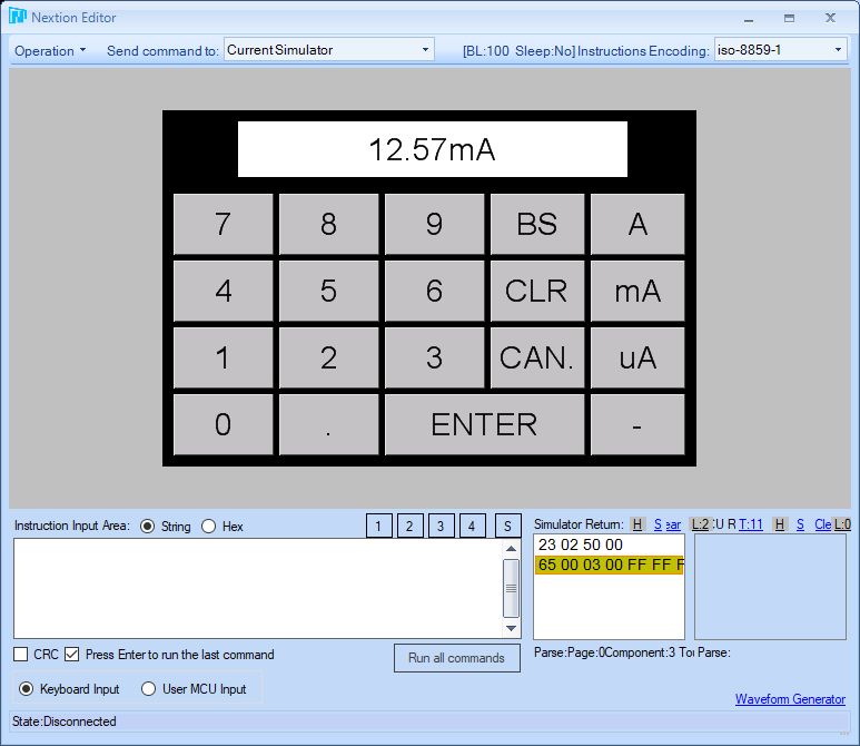
After watching a few
"Nextion keypad" Youtube videos, I learned enough to build a
numeric entry keypad. It was clear from these videos that it it
good to decouple the Nextion pages from the embedded code
as much as possible using its rudimentary string editing
capability. I should also use the Nextion Editor to do as much
UI development and debug as possible. I figured a keypad
would be a good learning project, particularly if I could add my
desired features: Numbers, Backspace, Clear, Cancel, Enter, and
units selection. By running this page along with my other
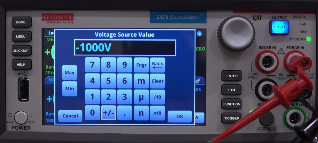
pages, I found this a fun and interesting exercise. I modeled it
loosely on the Keithley SMU pop-up keypad. Yes, I need to work
on the aesthetics.
Nextion Global
Variable Revelation
Inspired by this minor
success, I attacked the nemesis of my Nextion coding. Nextion is
intolerant of sending updates to a page that is not open, so If
you have an asynchronous operation like collecting data and
displaying it, then you can't send data to a widget unless it is
on the current page. You get an error message for each value sent,
and these error messages interfere with Nextion commands, making a
mess of missed commands. I couldn't get this to be reliable until
I controlled all page changes in my Arduino code. This required
many, many 'if' statements, as well as polling the page variable.
I thought I should be able to use global variables to solve this
issue. I searched the Nextion Instruction
page for 'global' to try this, but there is *no* discussion
of the use of global variables on that page. Finally in November
2021, Nextion Forum posted a discussion of the correct use of
global variables. It was in the Editor Guide.
Turns out if you use 't0.val=1234' on the wrong page, it doesn't
work and throws an error. But 'page0.t0.val=1234' does work as
long as the variable is set to 'global'! It only took me 9 months
to figure this out. Now I can simplify my UI coding considerably
by removing a lot of 'if (nPage == Main)' junk.
Recycle, Recover...
I had 2 complete Rev2's
and one Rev1 built up into 3 chassis. Plus one Rev1 spare board.
The Rev1's have the issue of over-current on the low current
ranges when applied voltage exceeds the clamp voltage. So I am
more careful with them, not using them as a load, so only 2
quadrant operation. Because of the time and cost invested in these
2 Rev1 boards, and the industry parts shortages, I'd been thinking
of updating them by adding the inverter. Problem is that I am not
fond of SMT hand-rework, requiring a dead-bug logic inverter and
at least 4 wires; pretty ugly. Then in the middle of the night I
remembered something I had previously considered: to use an unused
control bit instead of an inverter, and fix it in software! That
way only one rework wire is needed. One of the built-up units
already has a Rev3 Amp board. I build up a 4th unit, adding
another Rev3 Amp board. Amp boards are easy to build, lower cost,
and parts are readily available. Plus I can scavenge some of the
more expensive (> $1) parts from them.That brings the number of
fully functional DIY-SMUs up to 4 with minimal cost and effort.
Finally I can get one or two units into the hands of some other
users.
More About Temperature
Drift...
I dug further into the
V force path gain and offset drift, updating the drift tolerance
analysis spreadsheet to see what improvements could be made. I
found that 0.1% 25ppm resistors had significant drift when 2
different manufacturer's resistors are used. In the case of a
unit that drifted the worst, the 10K resistors that offset the
Force DAC, R12 and R15, were from different manufacturers. I
replaced the 2 offending resistors with two from the same reel.
It makes sense that 2 resistors from the same reel would have
better tempco matches than 2 arbitrary resistors, but it is not
good to depend on this.
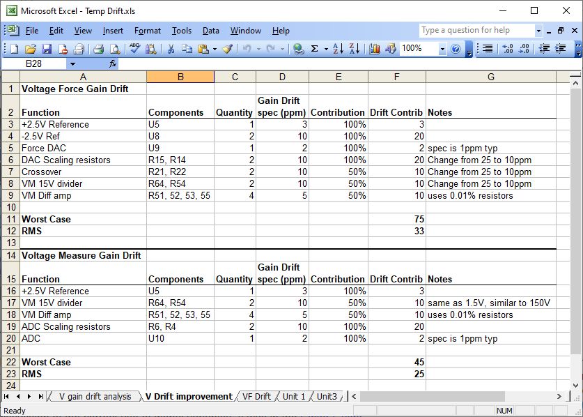
Here is the analysis of
drift using 10ppm resistors instead of the original 25ppm ones.
10K, .1%, 25ppm 0805 are about $0.15. 10ppm ones are about
$0.40. These reduce the force and measure drifts to about 1/2 of
the above spreadsheet. Further improvements can be made by
replacing the various 10K/10K pairs in the design with matched
2ppm networks such as SOT23 (Vishay MPM and others) for about $3
each. There are 6 of these 10K resistor pairs in the Force and
Measure Voltage paths, and a few more in the less critical
Current and Clamp paths. Is it worth another $20 parts cost?
Probably so if you are looking for the best accuracy or a wide
ambient temperature operating range. It would require a PCB
artwork change to use the SOT32 networks. Changing to 0805
10ppm parts is a simple BOM change.
Changing 10K resistor
pairs to a 2 resistor network works as long as there are no
other resistors in the stage that affect gain. Typically matched
resistors match for tolerance and for tempco drift, but not
for absolute tempco. So the drift won't match another
resistor. For example, look at The Force DAC buffer, R12, R14
R15. A Vishay MPM 10K/10K could replace R12/R15. These have a
2ppm/C ratio drift match, but only 25ppm/C absolute drift. So if
R14, th 2.15K is 10ppm, the worst case drift could be 25 + 10 =
35ppm. Worse than 2 10ppm resistors. In other cases where there
are only 2 10Ks, the drift wold be very good.
Since 10K/10K/2.2K
network is what's needed, a Quad 10K network such as the Vishay
ORN series could be used. These are 5ppm ratio drift and 25ppm
absolute in a SOIC8 package for a reasonable price: $3. I
simulated them with a 2K 10K, 10ppm fixed resistor to make up
the 22K, and they work well. This could be used in all 3 DACS
plus the two ADCs.
I checked the layout,
and as suspected, all the 10K/10K pairs have both resistors
close to each other. So the layout change to SOT-23 networks
would be pretty easy. I thought of making a clever (to me
anyway) small, hybrid footprint that could take either two 0805
resistors or a SOT-23. Too cutesy, and would confuse the BOM.
Besides I see exactly 5 10K/10K SOT23 networks in stock at
Digikey right now.
For now, I purchased
some 10K 5ppm and 10ppm resistors plus a few 10K/10K SOT23s.
I'll modify my worst drifting unit to add these parts.
12/2022 Update to
Component Shortages: Good News!
Finally, parts are
becoming available through distribution. The problem children have
returned! I can build more units. My beloved Si8661, AD5686,
AD7190, ADR421, OPA145, OPA2145, DG441, OPA2340, RS3-1215D are all
back in quantity stock at either Digikey, Mouser, or both.
Teensy 3.2s are still out to March 2023, but Teensy 4.0 can be
substituted. I haven't tried this yet. Nextion LCD, 12V power
supply, toroid, AC in, all no problem.
This is great news for anyone planning to build a DIY-SMU.
My plan is to work on the firmware (ADC speed, SCPI
updates...) and to see if a small production run of boards
would interest people.
2/2023 PS-Load Update
I've been working on
updating PS-Load,
implementing a new CPU and new large OLED display. See the PS-Load
page. I plan to use PS-Load to test batteries and solar cells, as
well as using it for a high-resolution power supply. It can
augment the 100mA range of DIY-SMU up to 3A supply and 5A load,
and for low cost. Great for testing high current transistors
(below).
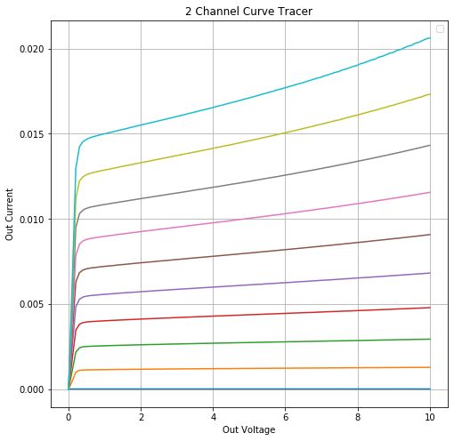
3/2023 DIY-SMU Curve
Tracer Working!
Here is an example of two
SMUs and some python code testing an old 2N2222 NPN transistor's
characteristic curves. One SMU drives the collector-emitter
voltage and the second one drives the base current. Base
current steps are 10uA each, so 0 to 90uA. "Out" means
Collector voltage / Collector current. You can see how the Beta
increases with collector voltage. And how the collector current
varies with collector voltage. I'm real pleased with the results.
Next is to adapt the code to test NPN transistors, power FETs,
high voltage up to 150V transistors, and vacuum tubes, again, up
to 150V. Cool! I plan to have the unit
This is a 2N2222, 10uA per base step
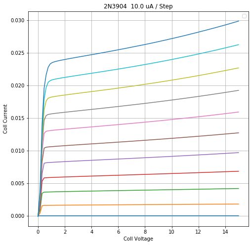
The instrument is doing 10 scans of 100 samples or 1000 samples
total, and takes about 2 minutes to collect the data. Smooth
curves like tubes can use fewer samples.
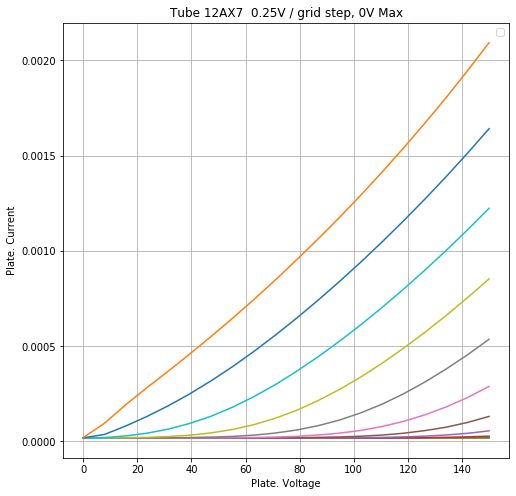
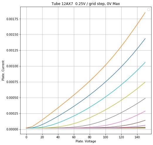
Here is DIY-SMU testing a vacuum tube, 12AX7 dual triode, parts 1
and 2, showing the matching of the 2 parts.
3/2023 DIY-SMU covers
I have 4 units with no
covers, got tired of cleaning the dust off the innards, and
fabricated a 3-sided cover for DIY-SMU. Bending sheet metal with a
Harbor Freight bender isn't so easy. I learned that 6061 aluminum
is hard to bend and can crack, and that 5052 is easier. Good to
know. I built some simple flat-metal top covers for the
other units. Covers are good.
Teensy 4.0 Processor
As of March 2023, Teensy
3.2's are unobtainium until 2034! Time to change to Teensy 4.0. I
bought and programmed a T4.0, setting the clock to 160MHz, close
to the T3.2 speed. This is to keep the current draw down. The
processor, LCD, and fan at slow-speed operate from +5V through a
linear regulator from +12V, and this regulator gets warm.
Good news, Teensy 4.0 just works!
As usual, don't forget to cut the power jumper on the back of the
module.
Page 1: the Analog part
Page 2: the Digital part
Page 3: Board Bringup
Page 4:
Board Bringup 2
Dave's
Home Page
Last Updated: 3/18/2023