DIY SMU: Source
Measure Unit Page 4: New Case, CPU, SCPI, Testing
The Schematics, PCB
files, and BOM are here
Page 1: the Analog part
Page 2: the Digital part
Page 3: Board
Bringup
Page 5:
Board Bringup 3
EEVBlog
Forum Page
Youtube
Videos
New Enclosure
I'm working on the new 2U
Half-rack (8.5" wide) case. Thanks to an ad in Nuts and Volts
magazine, I learned about GoBilda
hardware: an Erector Set for adults. In addition to motion
control hardware for robots, they make the 1106 off-the-shelf
rails that are nice for building boxes. These are 8mm square rails
with 4mm holes on 8mm centers. The ends are threaded for M4
screws. To build a box, the flat front and rear panels can screw
to the rails, the bottom and sides can bolt on with screws and
internal nuts. The top cover needs to mounted with some type of
blind screw threads. Current thinking is to drill and tap some of
the 4mm holes to accept M5 screws.
The top, bottom and sides are simple rectangular sheet metal with
a few mounting holes. Holes on the bottom are for mounting the
various components. These will be 16AWG (0.060", 1.5mm) 6061
aluminum. I generally cut rectangular sheet aluminum on my
table saw using a soft-metal carbide blade.
The front and rear are either hand-made sheet metal, PC boards, or
custom aluminum panels such as PCBWay. I plan to use a PCBWay
aluminum panel for the front. It solves the problems of front
panel finish color (using soldermask) and labeling (silk Screen).
Color choices are somewhat limited for PC boards and PCBway, but
so be it. As an EE I like to do front panel layout using PCB
design tools.
I have built similar chassis using 1/4" square aluminum myself,
but the rails are a pain to make: lots of machining, drilling,
tapping. My thanks to GoBilda for doing the hard part. 280mm
(11.0") rails are $6 each, and they come in different lengths.
Parts are on order.
For the front panel jacks, I plan to use 8mm (5/16") holes for
5-way binding posts. These allow more connection choices than
Safety Banana jacks, but are not as safe. The 6 holes can be
enlarged with a step-drill if you prefer safety jacks or other
connectors. For connections I plan to use the 2x3 arrangement that
Agilent uses. It is similar to what Keithley uses on their rear
panels, except I replace their Guard sense (not super useful) with
a Chassis Ground.
The heat-sink and mounting for the Amp board need to be raised up
a bit to clear the 8mm rail. 0.5" board spacers will do the trick.
The heat-sink will be 0.250" x 2.5" 6061 bar stock, cut to length,
drilled and tapped for the TO-220 transistor mounting hardware.
This will be screwed to the chassis-side for mechanical support
and thermal contact.
Open issues: Finalize front panel controls, lay out the Front
panel / CPU board, paint finish for top, sides, bottom, rear. And
cooling air holes.
CPU and Front Panel
Board
Now that I have decisions
about the front panel size and shape, control positions, and jack
configuration, it is time to design and lay out the CPU board. It
will have the Teensy Processor and the front panel encoder and
buttons, and power, Main Board, and fan connections. It fits
between the Nextion Display and the Instrument banana jacks. This
board takes in +12V and has a linear regulator for +5V. It has a
simple fan control from the processor. Since the processor can
calculate the power being dissipated in the heat sink, it can
figure out when to turn the fan on. The fan driver will run the
12V fan at low voltage (5V) and low speed when not dissipating
much power and will turn it on to +12V when over a few watts are
being dissipated.
I chose thru-hole, 6mm switches since they are multiple sourced,
and many button styles and heights are available. I prefer the
look of rectangular buttons, but have no easy way to make small
rectangular holes in sheet metal. So for home-made panels, will
use round buttons and holes. I can use the nicer rectangular
buttons when I get machine-made front panels.
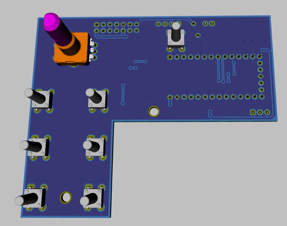
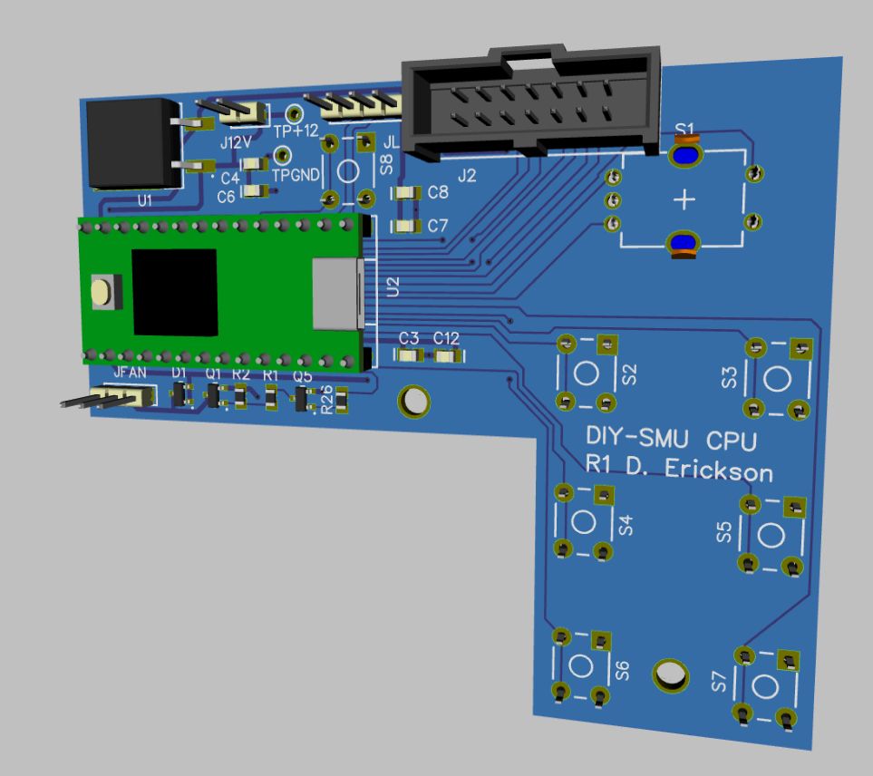
The CPU board front side has the controls, back side has the
Teensy 3.2 processor, voltage regulator, and the various
connectors.
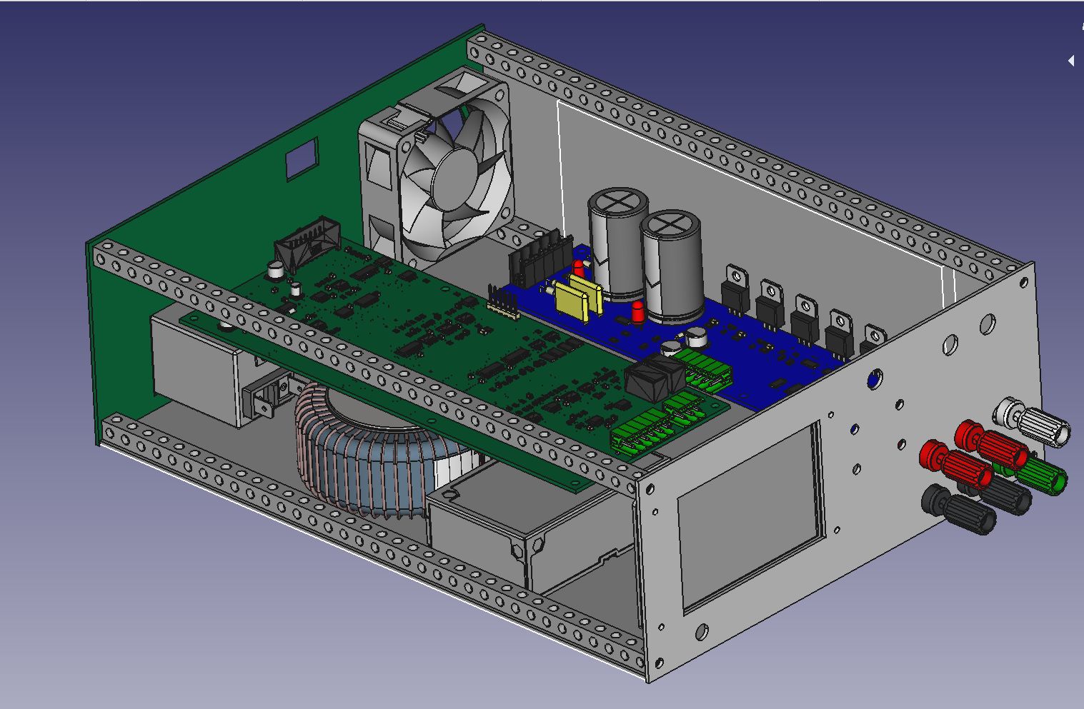
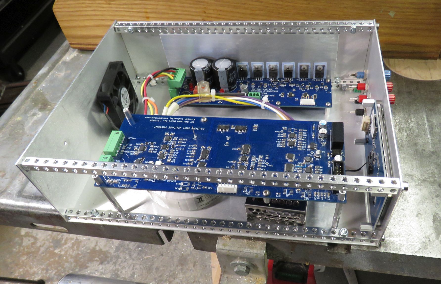
Here is the CPU board inside the new case. It fits nicely in CAD.
CPU Boards and parts are on order. Designing the hardware was the
easy part. The part that scares me is to port the firmware from
Arduino Leonardo to Teensy. I use some chip-specific timed
interrupt routines for reading and de-bouncing the switches and
encoder. Have never moved this code to Teensy, so I need to pay
the price for writing it as non-portable code. Ah well.
- Nextion Display
- SPI code. Could
bit-bang initially to get it working.
- Controls: Buttons
and encoder (needs 1ms timed interrupt)
- Fan control
(calculate power, turn on Fan)
Here is the prototype
enclosure with front, rear, one side and bottom. Gobilda.com
makes the 8mm corner rails. The 6 sides are rectangular, flat
0.060" (1.5mm) sheet aluminum. I patiently await the new CPU
board.
While waiting for the
CPU boards, I spent a few hours porting the code to Teensy and
getting it basically working. This required:
- Defining the I/O pin
numbers for the new board
- Moving the 1mS
interrupt from the AVR timer to a Teensy timer
Fortunately my 2019
Polysynth
project already had a timed interrupt routine for Teensy, so it
was easy to just copy the few lines of timer setup code. And it
worked! I had to fix one minor bug which the AVR compiler
called a warning but the Teensy compiler called an error. It
looked like 99.99% of the original code would just work. So
instead of forking off a new build for Teensy, I just use #define
AVRMEGA or #define TEENSY and where needed, #ifdef commands to
make the code do both. So far so good.
When it compiled OK, I ran it on a bare Teensy 3.2, and it output
the correct serial messages! I connected a Nextion display (just 4
pins) and Nextion worked. Porting to Teensy was much easier than I
had expected. My thanks to Seitan for making his Nextion library
portable.
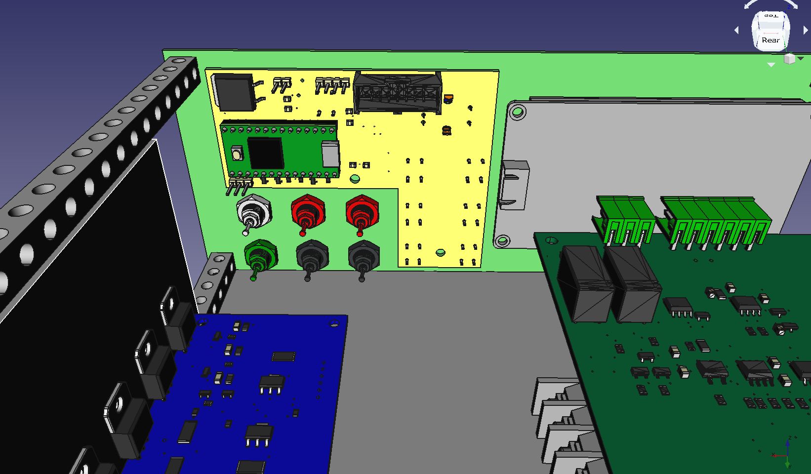
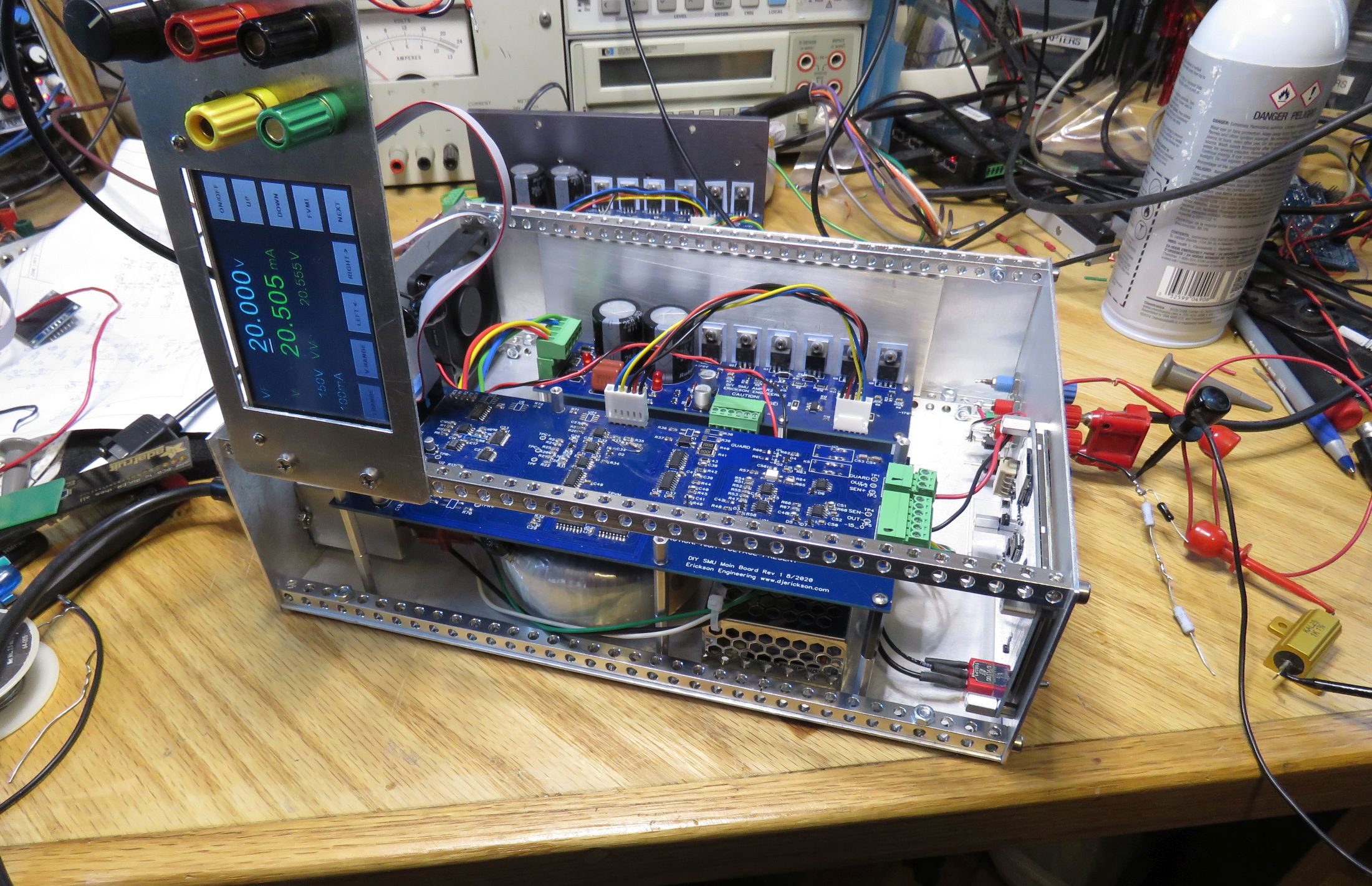
All the major components are installed, except the new CPU board.
So to get it working, the old front panel and CPU board are
mounted at an awkward location.
2/8/21: The bare CPU boards arrived from PCBWay today. The 5V
regulator, processor and Nextion display came right up, and the
SPI pins had activity. I connected a 14 pin ribbon cable to the
Main board and the encoder and buttons worked. It actually
controlled the SMU, and it works, time for a beer! Tomorrow I
drill holes in the front panel for the controls and mount the
sucker. I found a few small bugs in my code that I was able to fix
quickly. There is nothing like porting your code to a completely
different architecture for finding bugs.
When you use a Teensy and provide it with local +5V power, like I
do, don't forget to cut the power jumper under the USB connector.
Otherwise Your +5V will try to power the USB power and draw a lot
of current.
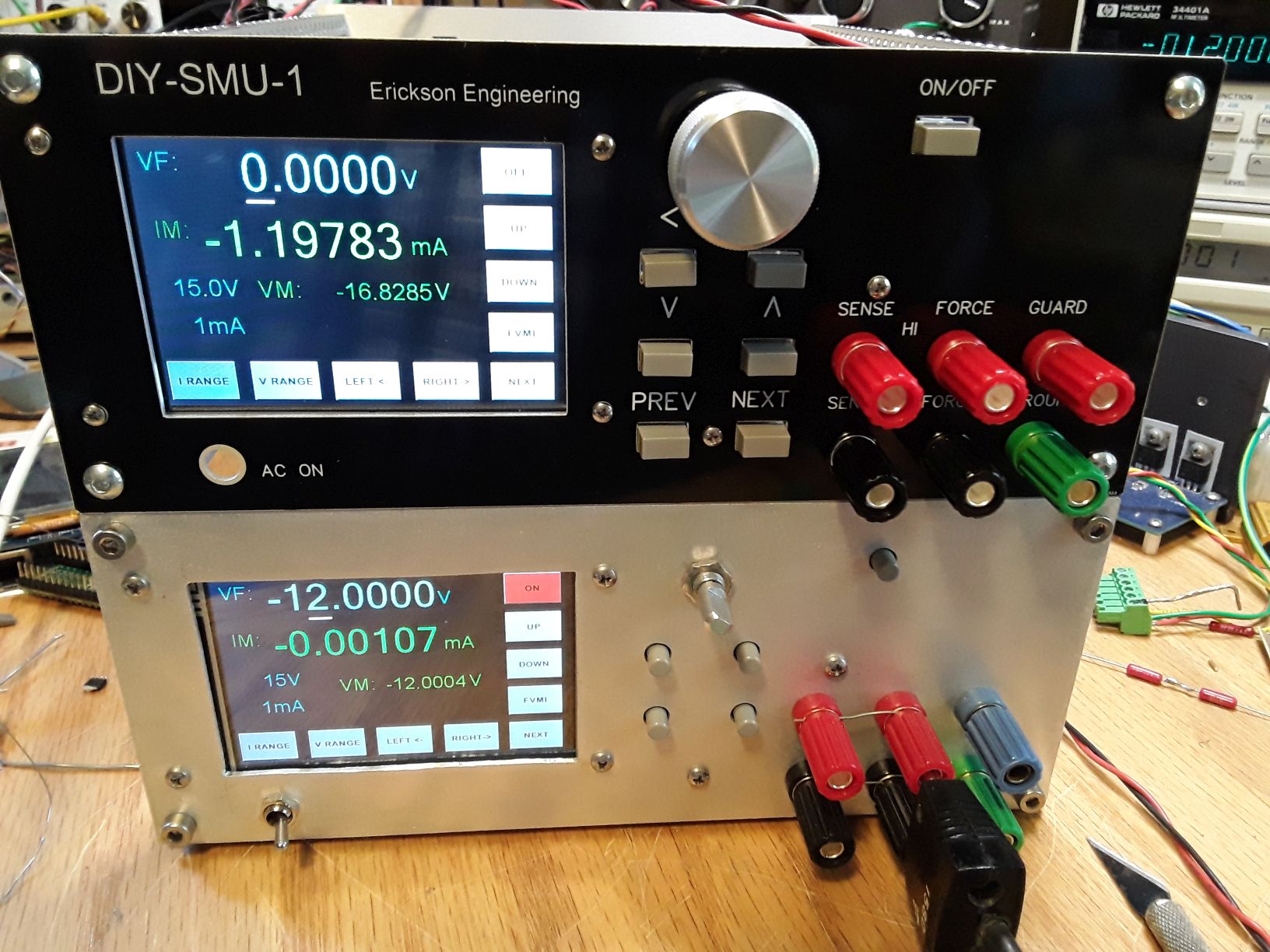
Here is the new case with the new CPU, all cabled up and working.
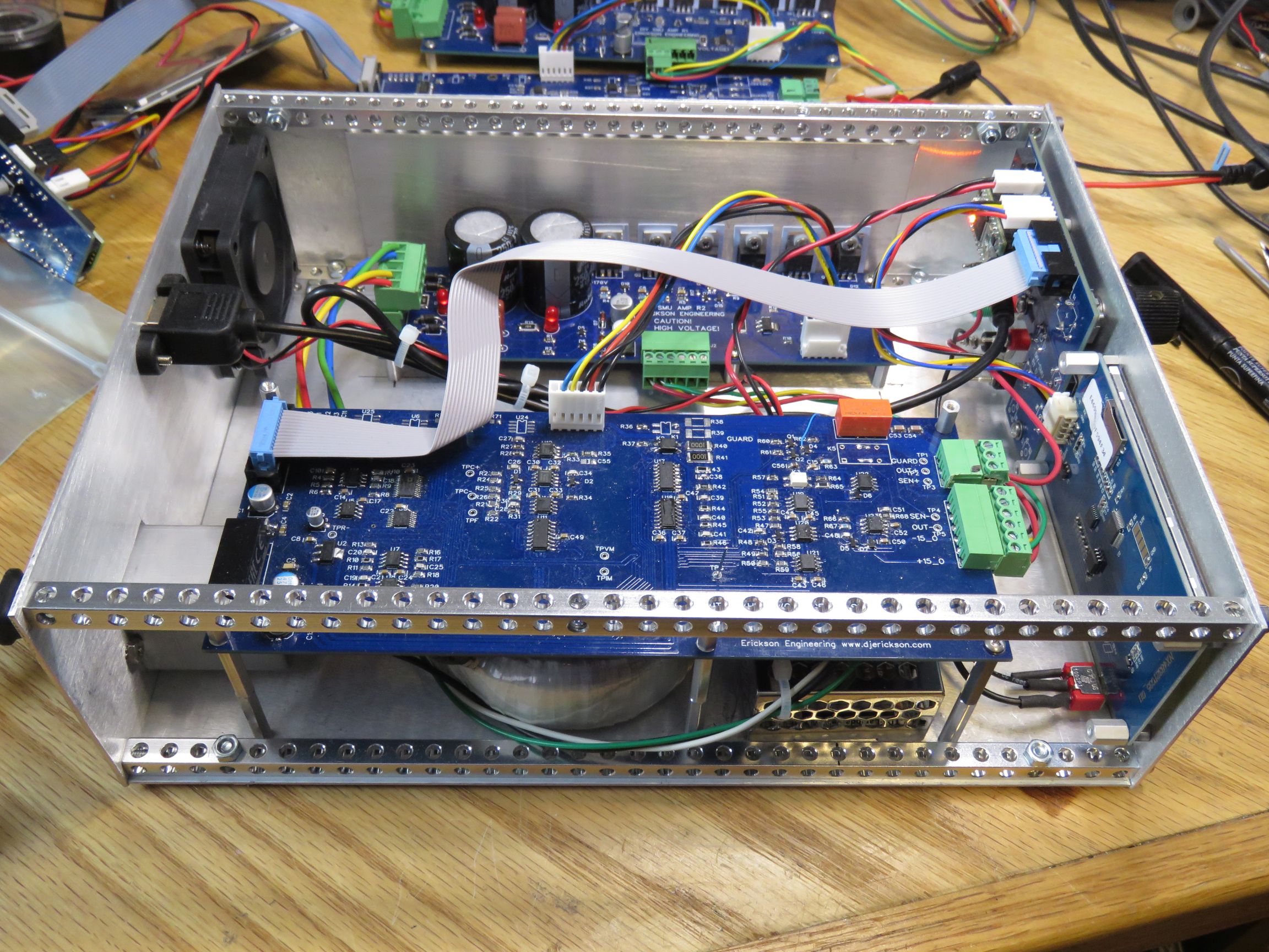
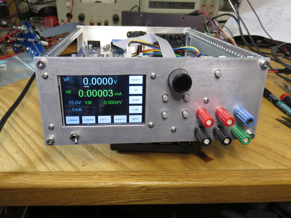
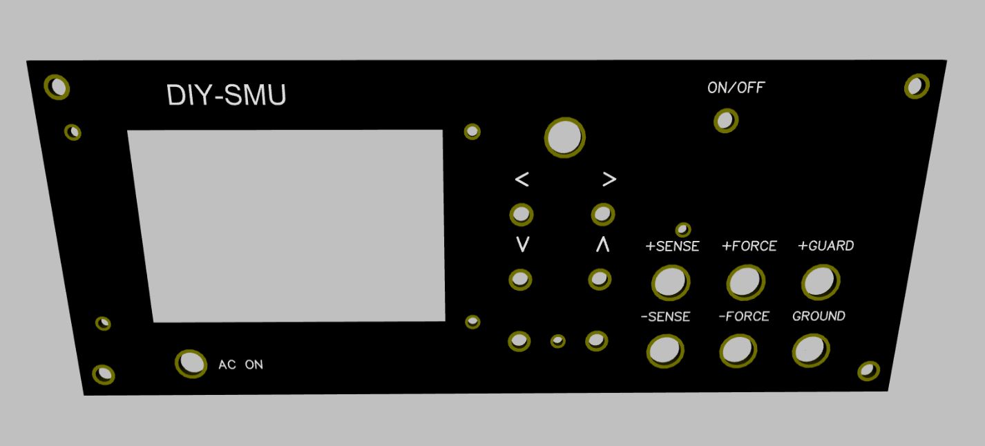
Above is the hand-made prototype front panel. Next version will be
machine-built and have proper labeling. Something like this
(below). Haven't decided the colors, but am limited by the normal
soldermask and silk-screen colors: White, Black Blue, Red, Yellow,
Green. Silk screen is black or white. I plan to use larger
rectangular buttons so the buttons cutouts will be changed. And
I'll change the jack labeling from +/- to HI/LO. And add a cool
logo. Haven't yet decided what to do with the bottom 2 buttons.
Maybe Remote sense and Mode.
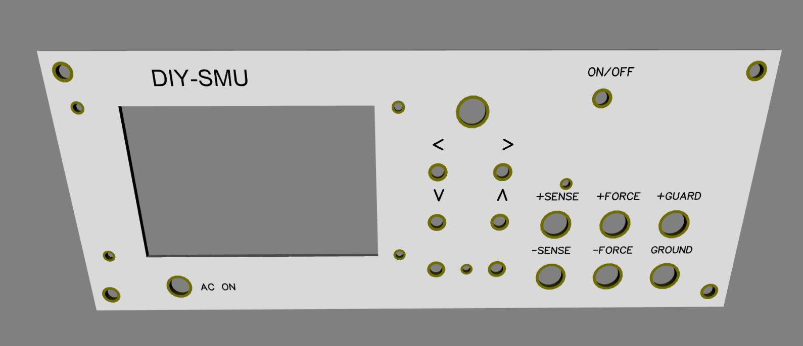
Or...
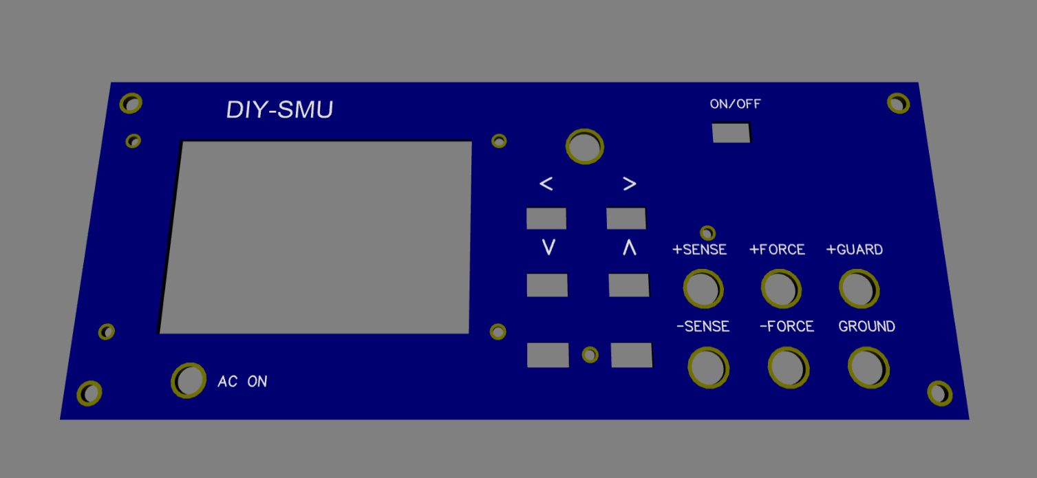
How about blue with the cool square buttons.
New Stuff: 1.5V range
and Remote Sense
I am working to add the
last few hardware functions: 1.5V voltage range and remote sense.
1.5V was fairly straightforward, consisting of a SSR (Solid state
relay) that reduces the force DAC gain by 1/10 and the software to
control it. I was concerned that the SSR would have minor leakage
and could affect the 15V and 150V ranges. I tried heating up the
SSR and no change in 15V. The fact that a 60V switch is only
switching +/- 5V helps keep leakage low.
Next is the remote sense relay. I installed the relay and created
a function to control it. It works fine as long as the remote
sense terminals are connected to the source. But as I suspected,
when the sense leads are disconnected, the sense inputs float, and
so the sense voltage is off by as much as several (10 or more)
volts. The usual way to address this is to have a high-value (like
100K) resistors from the local sense to the output. But should the
resistor sense the output before the output relay or after? Hmmmm.
As long as the firmware always sets remote sense to LOCAL when the
Output relay is OFF, it shouldn't matter. The problem is when
remote sense is REMOTE and the output relay is OFF. For this
rev board, I'll just be careful to keep the remote sense LOCAL.
And will add the resistors to the Rev2 artwork.
I see that the K236 does not have these high-value resistors. Not
sure why not, since it seems much safer to include them. It seems
easy to have a remote sense lead(s) disconnect somewhere, then
your voltage / current source is running semi-open-loop. Maybe
it's because the K236 uses Triaxial connectors, so it's hard to
disconnect the Sense without disconnecting the Force. Much easier
to make the mistake with banana jacks.
The downside of using 100K local sense resistors is that they
cause a remote-sense voltage error by the ratio of the two local
sense resistors (100K (Rls) and the 2 remote sense wire
resistances (Rw). And the voltage drop in the Force wires and
force relay (Vd). The error is ~ 2 * Vd * Rw / Rls. With 200mV
drop in the wires and 1 ohm (kind-of high) remote sense wires, the
error is ~2 * 0.100V * 1ohm / 100K = 2.0 uV. Not bad at all. Hey
this is a DIY project: if you hate the 100K's, just un-solder
them. Or use <<1 ohm sense wires.
Problem: Voltage clamp
in the presence of an external voltage
With FVMI, the clamp is a
current. This is a fairly safe mode since the current is always
limited by the current clamp, no matter what the voltage. But
there is a problem with FIMV. Voltage clamps cause the
voltage to be hard limited. But if you allow clamping of voltage
and apply an external voltage that is outside the clamp range, the
current can get very high, limited by the coarse current limiter
on the amplifier board, about 150mA. The old irresistible force /
immovable object problem. This protects the amplifier, but not the
more delicate current shunts and current range switching. I fried
at least one 10mA (499 ohm 1/2W) current shunt and its CMOS
switch. I'm trying to understand the problem better and to come up
with a solution.
I ran the Spice simulation of FIMV mode, set current force to
10mA, set the voltage clamps for +/- 15V, and tied a 22V source to
the output. The simulation won't stabilize (a bad sign) unless I
put a 100 ohm-ish resistor in series with the 22V load. On the
10mA range, sure enough, the current increases to 33mA or higher.
High enough to cook the 499 ohm current shunt as well as the DG441
CMOS switch. Then (in the middle of the night) I remembered that
the Keithley 236 has FET switches to control the amplifier's local
current limit. There is a high range and a low range. The high
range is for > 100mA and the low range limit is about 15mA, a
safe maximum current for the 10mA and lower ranges. Another "Oh,
THAT's what that circuit is for!" moment. I will add this to the
next revision Amp board. It requires a 5V control signal that goes
HI for the High current range (100mA). The existing 100mA range
control bit is LO for the 100mA range so I either need an inverter
or another control bit. There are 3 free bits and a spare pin on
the Amp drive connector J2 on the main board.
Problem: Step-response
Overshoot!
Another engineer,
Jaromir, also built an SMU, based on the K236 with inputs from my
design. He noticed that with voltage steps, there was about 10%
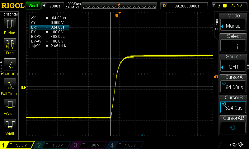
overshoot, followed by a short settling time. I Let him know that
my unit exhibited a nice well-damped step response: exponential,
with no overshoot. Here is a 200V step response. No overshoot, but
perhaps a bit slow, about 400uS to settle.
I had 2 systems, and had not tested the step response on Board #2.
When I tested it, I saw similar response to what Jaromir reported.
Hmmm. I compared the two boards carefully, even removing some
components to measure them accurately. There were a handful of
differences between the two boards. Board #1 had been used to
debug many initial problems, and some of these changes hadn't been
put back.
- Force DAC filter
capacitors. No difference.
- Integrator P term
resistor R27: #1 had 1K, #2 had 2K. Changed, no difference.
- Checked most of the
compensation caps: no difference.
- Checked value of Y
capacitor C5, #1 had none. No difference.
- There was no C34 on
#1, no difference.
- #1 had no output
relay installed. I installed it and no difference.
- I installed #2 in
the enclosure, so the power CPU and mostly, the Amplifier
Board were different. It still had overshoot.
Finally after
implementing all the changes, I re-tested #2 and the overshoot was
fixed.
LVGL?
I started messing with
the new graphics library, LVGL. While I wait for 3.5" 480 x 320
panels to arrive from Asia, I started learning LVGL. First I went
to LVGL Academy. The first
intro video courses are free, and the full course costs $25; well
worth it. Then I installed the LVGL simulator, based on Visual C.
There are other versions available for Eclipse and other IDEs. The
simulator requires Visual Studio Community 2019. I haven't tried
it on the newer Visual Studio Code yet. Then install Python, then
install the simulator. Then the examples run. They pop-up an LCD
display window which responds to mouse commands. It's all new, and
I'm just beginning. Of course everything is completely different
from Nextion. To start with I'm trying to set up a display similar
the Nextion one: A few numeric and alphanumeric test displays, in
small and large fonts, color fonts, and some type of cursor.
I was able to get the NXP editor working. It is the first
drag-and-drop editor for LGVL. It is set up for NXP processors and
boards, but it generates generic C code.
I also bought a board with a Teensy and 3.5" LCD. Turns out it
also does NMEA2000, the boat data standard based on CAN bus. But I
cannot seem to get their examples to compile. Worse, I can't get
the LVGL libraries working.
Vini from OSMU helped me get the STM32F746 Discovery kit working.
It is not Arduino, but runs LVGL nicely on the STM32Cube tool set.
One key feature I have used on several projects since my character
LCD days is unfortunately not available in these fancy Graphics
libraries: a simple underline cursor. Or a block cursor. I use
this to set individual digits of a number. This is particularly
useful with 5 or more digit numbers. With an old character LCD,
it's just there. With OLEDs, I had to calculate the position of
the characters and put a line underneath the right character. Same
with Nextion. But the SMU has many values to set, and many are
range-dependent. The simple Cursor code gets ugly fast. LVGL has a
widget that is close, their Spin Box. But unfortunately its cursor
is a bit cumbersome, and I see no way to get rid of the clunky +
and - controls.
I decided that LVGL isn't ready for us mere mortals yet. I'll
continue using Nextion.
SCPI Control
For SCPI I found 3
libraries: 2 are Arduino Libraries: https://github.com/LachlanGunn/oic
and https://github.com/Vrekrer/Vrekrer_scpi_parser.
Vini from the OSMU project has been helping me. He pointed
me to the full-featured SCPI library: https://www.jaybee.cz/scpi-parser.
One of OIC's examples implements a simple Source-Measure unit
using Arduino ADC and PWM pins. This is a perfect example. I
tested the parser code by sending various number formats for the
voltage settings: Integer, fixed point, and scientific notation.
They all work well, which is wonderful. Now I'm changing the
example to implement ranging, current measure, etc. Nice
job, LachlanGunn! I'll try out the Jaybee parser as well.
Vini is helping to get SCPI working on the SMU. But meanwhile, I
want to get experience with SCPI, and also want to implement it on
older and future projects. I began with the OIC library. I got it
working on a Teensy, and was happy with how quickly it came up. My
18b DAC project was crying for a proper way to control it via USB.
And it is a simple enough project: *IDN?, *RST, set and get the
DAC to a voltage, done!. See the 18b
DAC project for details. I tried to install all 3 libraries.
OIC and Vrekrer worked well. Jaybee is much larger, with 8 .c
files and 10 .h files. I could not get it to compile on Teensy. I
settled on the Vrekrer library. It is simple to use and works
well.
My next step was to use the 18b DAC as a test platform for
additional SCPI commands. This worked out well without the
complexity of all the SMU code.
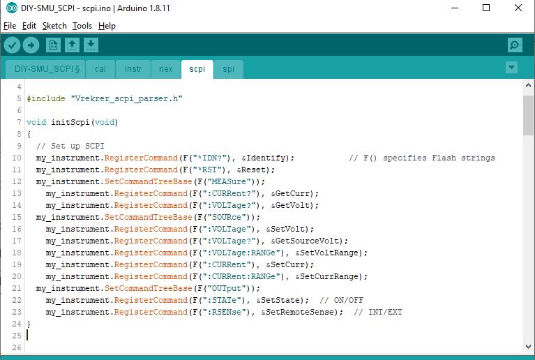
Adding this library to SMU on Teensy went fairly smoothly. I found
that I needed to control the SMU data structure variables, set the
hardware, and update the display. This forced me to refactor
several additional control functions such as setOnOff(). It's all
good. Here's the first pass SMU SCPI command list, containing the
major settings.
Measurements and error
plotting: ADC errors
As rewarding as it is to
type in SCPI commands and see them execute, it is far more
exciting to write a program to control instruments via SCPI. For a
control program, I am currently using Python Spyder and pyvisa.
For the first time I can automatically sequence through a voltage
or current range and compare the output of the SMU to my 6.5 digit
DMM.
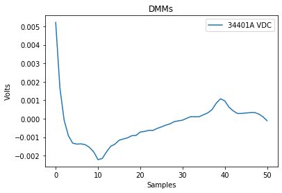
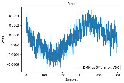
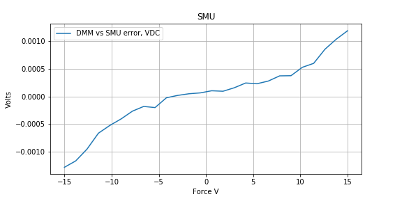
This first Python plot compares SMU Measure to the DMM over a -15V
to +15V voltage range set by the SMU and shows the error. Note the
mirror-image bumps around -9V and +9V. The rise at -15V is another
error. Is it the voltage measure circuit, the ADC, maybe my DMM? I
suspected the ADC input op-amp U4, a TLC2272A. The large rise on
the left is the op-amp output near VCC, something else to look out
for.
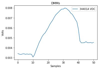
I changed U4 to an MCP6072, another mid-precise 5V RRIO part I
have used in the past. The ~6mV offset error is because it is not
re-calibrated. Completely different error shape! Similar dip at
-9V though.
This argues that the gross error shape is the non-linearity of
amplifier U4, and not the ADC or the DMM. The results are very
interesting. I purposely use an inverting amplifier for U4 in a
current-summing configuration to minimize any non-linearity caused
by input common-mode variation, a problem with many RRIO
amplifiers. The amplifier + input is GND, and the output is biased
to mid-scale by a very precise reference. This amplifier is
operating at a gain of 0.55: +/- 5.5V input range, 0 to 5V output.
It looks as though the op-amp input error varies as a function of
the output voltage. Something that no op-amp specifies! Over a 30V
range (+/- 15V) a 5mV error is +/- 0.008%: significant but not
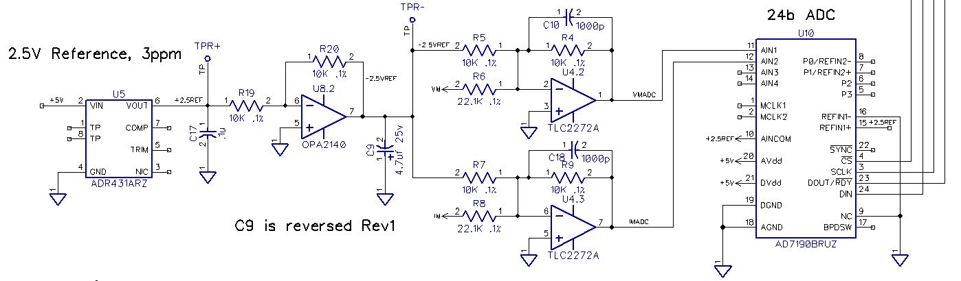
terrible. Here is the schematic for the ADC input buffer, U4. U4
is powered from +5V and GND. I will try some other op-amps.
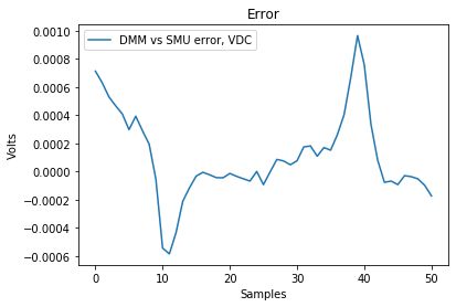
By the way, here is the Force error, effectively the DAC and
system INL, 500 samples, over a -15V to +15V range This is about
1mV p-p or +/- 0.5mV. The force DAC is bipolar 16b, the ADC is
about 23b. So the 5mV ADC error is concerning. The ADC error
should be should be < 0.1x of the DAC, not 5x worse than the
DAC. I plan to use the Measure ADC to calibrate the Force DAC. Not
until I fix the ADC errors.
Here is the new OPA3240. This is a 5V RRIO part with better input
and output specs near the rails. I re-calibrated the 15V Measure
range to correct for offset and gain (slope). This is
better, note the scale: about 1.2mV p-p. Still the mysterious
bumps at +/- 9V. Roughly 25% and 75% of the ADC input range of 0
to 5.0V. Hmmmm.
I tried turning the AD7190 ADC input buffer ON. It has been OFF
until now. With the buffer ON, the ADC loses about 0.25V of input
range near each rail. No difference was measured since my circuit
does not go that close to the rails. So it's not a ADC
buffer-related issue. Next I'll try some chopper amps,
OPA2333. OPA2333s arrived, I soldered one in. No change. The
two peaks are still there, and about the same amplitude. That's
the 4th opamp. It's not the opamp.
So it must be the ADC. I read the entire AD7190 data sheet and
found a few small issues, plus a hint. The INL spec is 5 ppm Max,
1ppm Typ. And the INL graph shows a suspicious similarity to
my error plot, but at 1ppm, not 30ppm. The other 2 small issues:
- They recommend input
RC filters for common and normal mode to remove noise that is
near the internal sampling rate. I doubt this is it. Also this
is a note only, no schematic!
- Also improved
bypassing: short leads and separate Dvdd and Avdd.
I added a 0.1uF cap
from power pins 19-18 and 20-21. Slight change in gain, but the
+/- 0.5mV errors persist.
Added a 0.1 cap to the
Ref+ pin. The data sheet warns that the reference input is
dynamic, meaning it draws AC current. This shifted the peaks
from +/- 9V to about +/- 12V. Same amplitude though. This could
be a clue!
I tried some other ADC
settings:
- Chop mode. This
reduces small offset values and offset drift bus slows
conversion time 3-4x. No difference
- Filter select: This
trades off settling time vs conversion time. No difference
- Buffer: Worse with
buffer off, depends on op-amp driving.
- Convert time: Tried
longer and shorter settings, no difference.
I looked at the designs
of two eval boards for the similar AD7193. There is no AD7190
eval board, but AD7193 is the same ADC core and specs and a 8:1
mux. Nothing in the layout jumped out at me. However both boards
have a 10uF tantalum on the reference. I have a 0.1 uF only, per
the recommendation of the ADR431. When I paralleled a 10uF
ceramic cap, the evil error curve that I have been waking up in
the night thinking about for 2 weeks WENT AWAY! The AD7190 does
not call for specific bypassing on the reference input. Finally,
noise and error in the +/- 100uV p-p range out of 30V p-p.
that's 4ppm. Love it.

There is (as always) a side effect to this change. The ADR431
reference doesn't like large capacitive loads, which cause
high-frequency peaking (see data sheet) unless additional
compensation components are added. I will switch to the ADR421
which doesn't have this issue and also is lower noise: 1.7uV vs
3uV.
I implemented the ADC
and reference reworks to unit #2. It still has an ADC
non-linearity that is slightly different than than unit 1. There
is also a gain error that will reduce after calibration. But
there is still a symmetrical error curve of about +/- 0.4mV on
the 15V range. Since this is holding up the calibration process
(below), I will defer the final linearity correction to the next
PCB revision, and move on. Calibrating over the range of +/-
11.0V eliminates most of the non-linearity errors. Also the
34401A DMM voltage ranges are only up to +/- 12V. Scandal!
34401A really isn't 6.5 digits, which generally means 19.999V,
it's more like 6.2 digits (1,2000,000 counts). BTW, the HP 3478A
sold as a 5.5 digit meter is actually 300,000 counts so for
measuring 12V to 30V, it has the same resolution as the
34401A. By using +/- 11V, the 34401A does not
auto-range, which saves both measurement time and relay
operations.
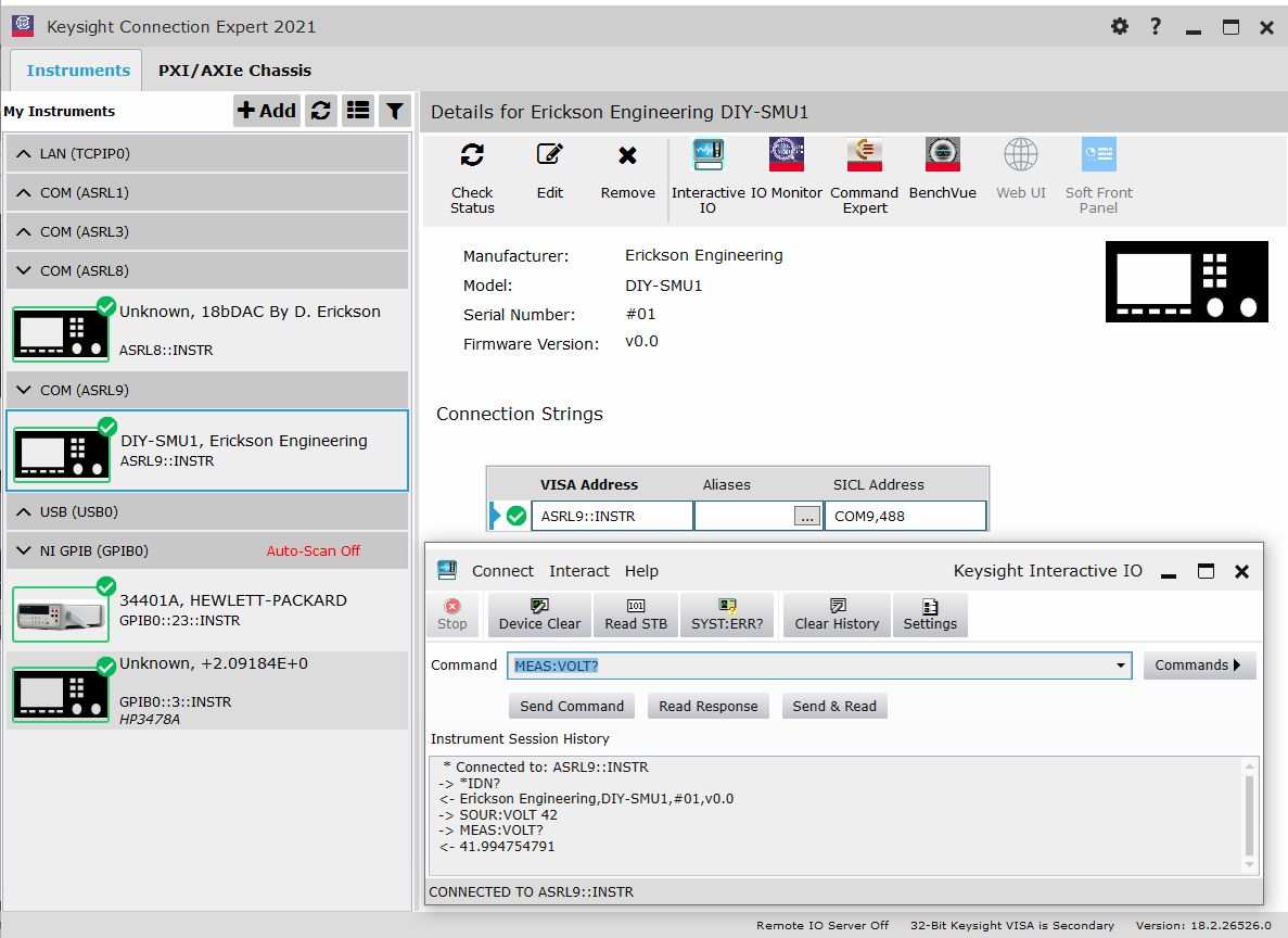
SCPI Instrument
Program
For a SCPI instrument
connection program, I use Keysight's Connection Expert. It
requires you to register and install 1-2 other programs. Here it
is controlling DIY-SMU, my 18b DAC and two HP GPIB instruments.
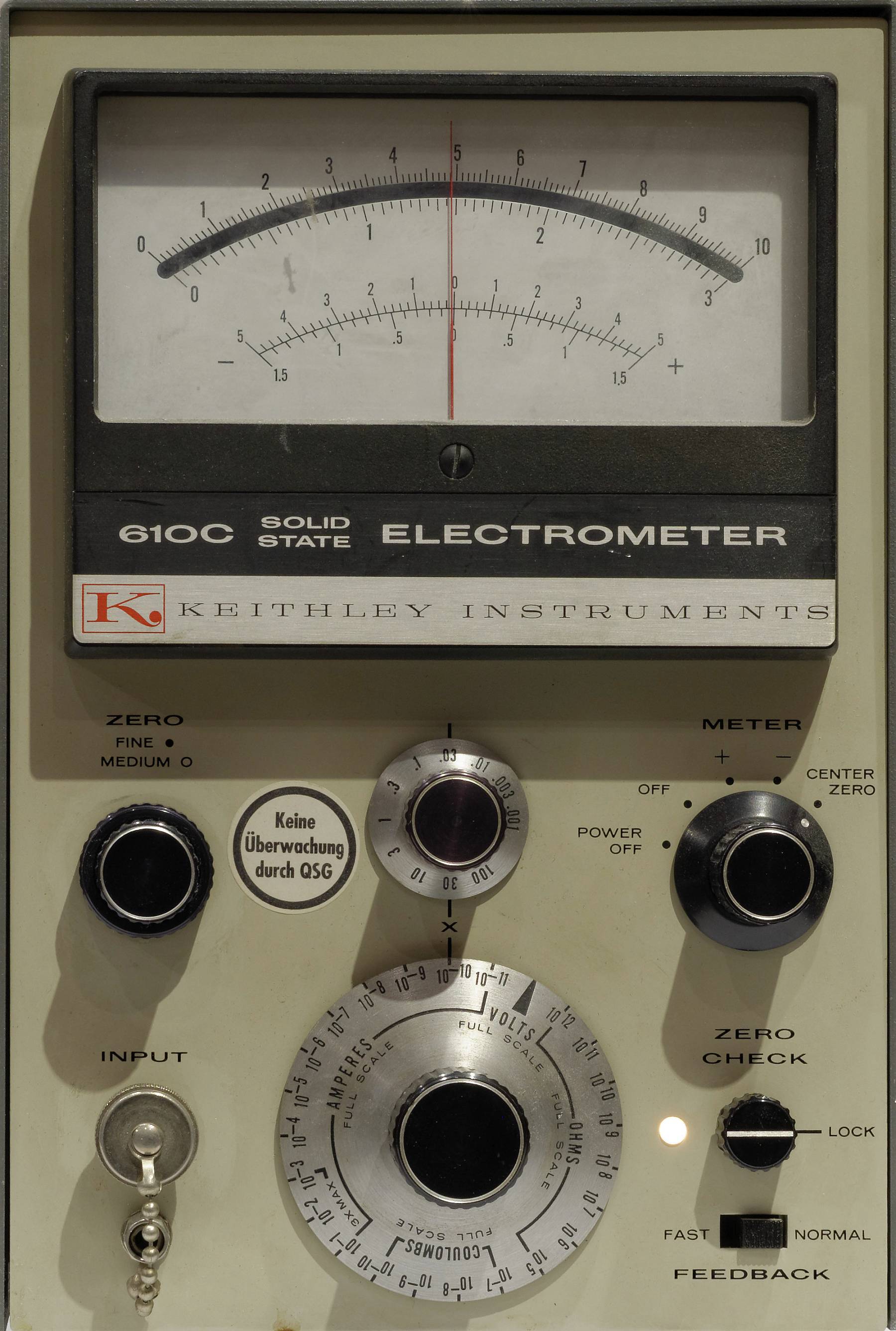
Very Low Source
Currents
To measure the lowest 1uA
full-scale force current range, I have been using a 1Meg precision
resistor, or the 1M/10Meg input of my scope and DMM. I have access
to a Keithley 610C Electrometer which measures extremely low
currents. The 610C lowest current range is 1e-11 x 0.001 or 10fA
full scale! Not sure what I can use to test this. It certainly
needs a shielded and guarded enclosure. Measuring SMU, it was
rewarding to see this meter stepping through 1LSB changes of the
Force DAC (~30pA) on the 1uA range.
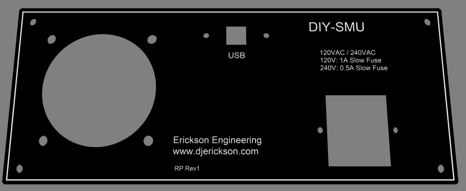
New Front panel and
Case
Here is the new front
panel mock-up. The panels were ordered from PCBWay, 5 for $50. I
moved the mounting rails in 1mm to better accommodate the cover
and bottom sheet metal. A one-piece, 3-sided cover is in process
as is a PCBWay rear panel. Each factory panel saves me hours of
hand sheet metal work. Let me know what you think of the
color. The cover will probably be light grey or greige.
Here is the new rear panel CAD model. Parts are on order.
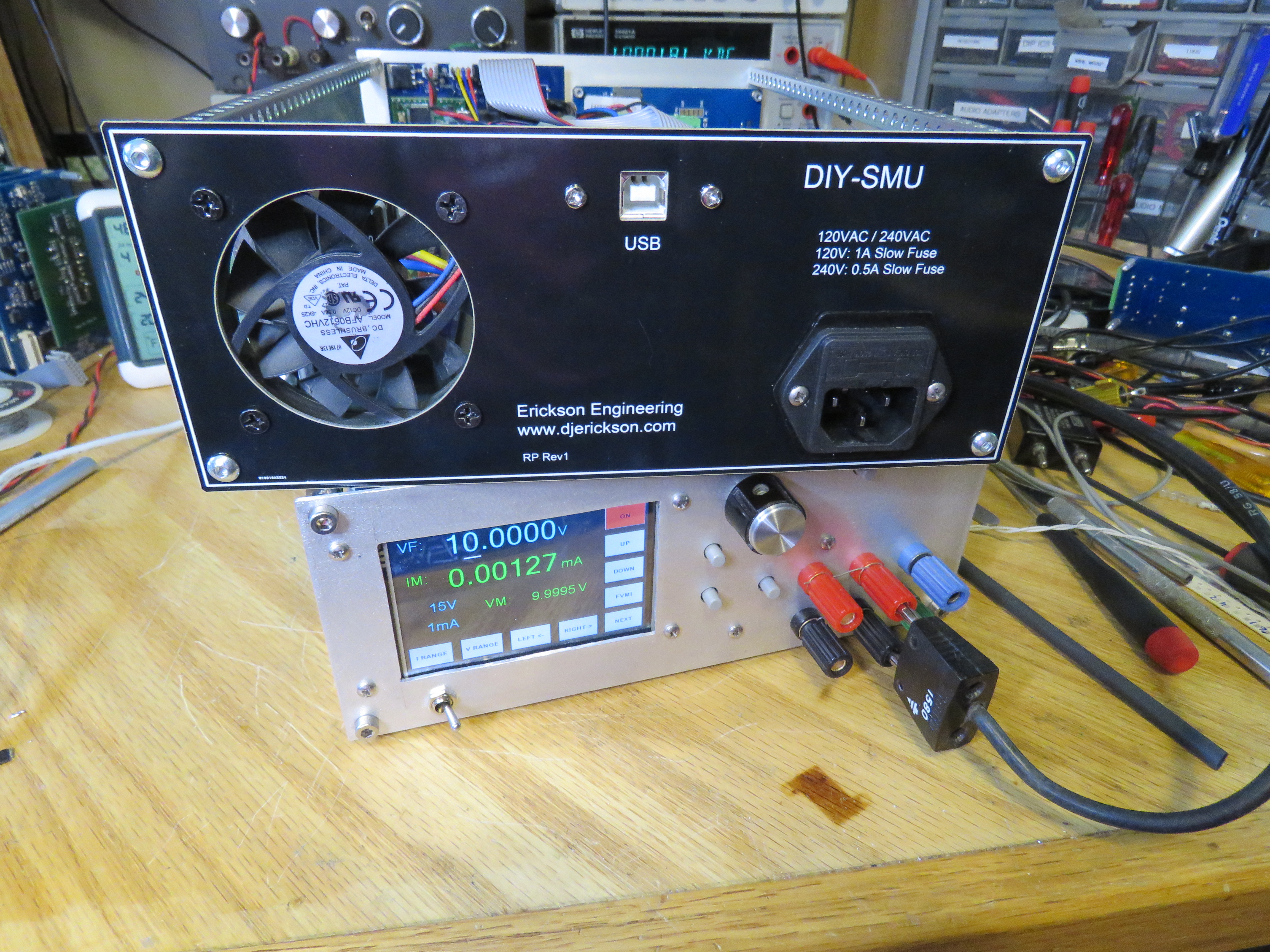
The new rear panels arrived from PCBWay. They look and work great,
just like the CAD model. What a joy it is to just screw in the
components: no measuring, marking, sawing, drilling, hole-sawing,
filing, de-burring, sanding, priming and painting. No blank
panels or crummy stick-on labels. Next task is to convert
the lower unit to the new chassis and panels.
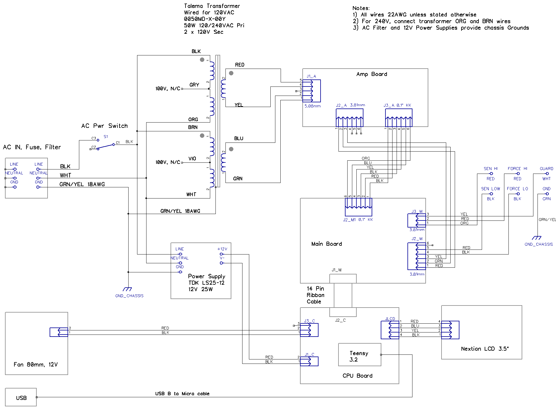
Chassis Wiring
It occurred to me that I
have all the chassis interconnect details in my head, and that
anyone building a DIY-SMU would benefit form a wiring schematic,
showing the chassis components, AC and DC wiring, and cables.Here
is the schematic.
Calibration Update
I have been working on
a new calibration method. Now that SCPI is working, it makes
sense to calibrate using an external program and external
instruments. I mentioned before the method I have been using to
calibrate
manually. I set
the force to 0V, and get a Force offset cal correction, entering
the value into the code and re-compiling, then repeating for
Force gain. Then repeating the process for both Force and
Measure on 3 voltage and 6 current ranges. Not pretty or fun,
not to mention error-prone. While testing the Force and Measure
linearity with Python, I found that taking a series of
measurements and then doing a least-squares linear fit on the
error data works very well. I use the Python np.polyfit()
function to provide offset and gain cal factors
simultaneously. The Python program generates cal factors
for each voltage range. I needed a way to pass the cal factors
to the SMU via SCPI. I chose CALibrate:VOLTage index, value to
send one single-precision, floating point cal factor at a time.
The index will use 0,1,2,3 for FVGain, FVOffs, MVGain, MVOffs
for the 1.5V range, then proceed through the other voltage and
then the current ranges. Values will be sent to RAM first, then
copied to EEPROM. Another SCPI command disables or enables
calibration: CAL:STATe ON/OFF. I also need a way to identify a
blank EEPROM and not load cal from it.
Next is Calibration of
the current ranges, and commands to copy the data to EEPROM. For
current cal, the cal program prompts the operator to manually
change the load resistor for each range. I built a handful of
precision resistors on dual banana plugs for this. I also
found and fixed a few bugs with Force current setting over SCPI.
Temperature Drift
Measurement
I tested one instrument
for temperature drift of Voltage Force and Measure over a 10°C
range, from 28°C to 38°C. The overall Force and Measure drift is
primarily caused by about 10 resistors, each contributing
between 1.0 and 0.5 of their drift to instrument gain drift.
These are mostly 0805 0.1% 25ppm/°C resistors, except for the
four 0.01% 5ppm ones used in the voltage-difference
circuit. The Reference, DAC and ADC are all in the 1-3
ppm/°C range. Here is a Voltage Gain Drift analysis spreadsheet
showing the temp drift contribution of each component in each of
the Voltage Force and Measure signal paths. RMS assumes Gaussian
distribution for the drifts, and uses the square root of the sum
of the squares. I calculate about +/- 60ppm and measured
+20ppm/°C for both Force and Measure drifts.
This spreadsheet is
useful to show the largest contributors to drift. To improve
drift, 0805, 10K, 10ppm resistors are available for about $.50.
Other value 10ppm resistors are about $1.00. 5ppm 10K's are
about $1.30 and other 5ppm values are about $2. The crossover
uses two connected 10K's which could be a SOT23 network to
reduce its drift to ~1ppm.
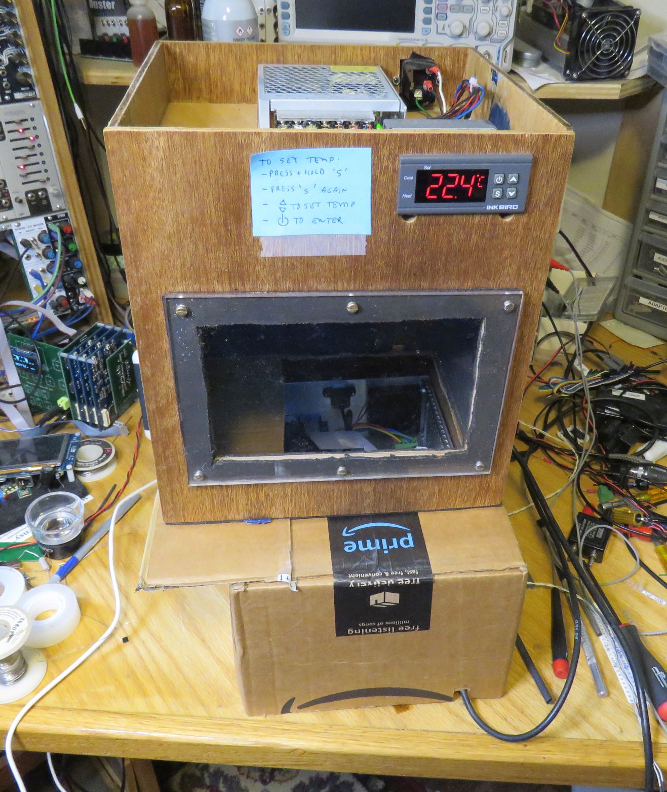
Here is my DIY bench-top temperature setup. The top box is a
small oven I built to test boards and components. The chamber
bottom is open to allow it to be placed over an experiment. The
bottom cardboard box is an adapter to allow the too-large
DIY-SMU to fit.
10/20/21 Updates:
Calibration Code
I completed the
calibration Python code and am happy with it. The voltage
calibration calibrates all 3 voltage ranges for force and
measure in one step. The current calibration requires changing
the load resistors for each current range. I created a simple
menu to select the current range and prompt the user to install
the correct resistor.
- 1uA: 1
Meg-ohm, 1V
- 10uA: 1 Meg-ohm, 10V
- 100uA: 100K, 10V
- 1mA:
10K, 10V
- 10mA: 1K, 10V
- 100mA: 10 ohms, 1V
My HP34401A Ebay meter
hasn't been calibrated in a few years. I'll get it calibrated in
order to get accurate resistance values for my cal resistors.
I still don't write the calibration values into EEPROM. The
calibration python code generates C code for the cal factors,
which you copy into the cal.ino file. Then you recompile the code
and go. This means that you need to manually select which cal.ino
gets used for a given unit. Here is typical voltage cal data
generated by the Python code. Note that the offsets are in the
tens of millivolts range and the gains are all within about
2%. If the cal values are out of whack, it means there is
something wrong with the hardware. I should add a limit test.
// Calibrated at 2021-09-17 11:06:22.578853
// 1.5 V Range Cal
Range[VRange_1_5].FGainCal = 0.98599201 ;
Range[VRange_1_5].FOffsCal = 0.00000794 ;
Range[VRange_1_5].MGainCal = 1.00229606 ;
Range[VRange_1_5].MOffsCal = -0.00187238 ;
// 15 V Range Cal
Range[VRange_15 ].FGainCal = 0.99274970 ;
Range[VRange_15 ].FOffsCal = -0.00155500 ;
Range[VRange_15 ].MGainCal = 1.00230964 ;
Range[VRange_15 ].MOffsCal = -0.00187619 ;
// 150 V Range Cal
Range[VRange_150].FGainCal = 1.01223362 ;
Range[VRange_150].FOffsCal = -0.01591642 ;
Range[VRange_150].MGainCal = 0.98301726 ;
Range[VRange_150].MOffsCal = -0.01869274 ;
Page 1: the Analog part
Page 2: the Digital part
Page 3: Board
Bringup 1
Page 5: Board Bringup 3
Dave's
Home Page
Last Updated: 3/7/2023